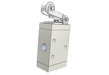
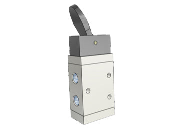
174 products

M3 Series Valve

M3 Series Valve

  • Product Features
  • Specifications
  • Product Ordering Code

Product Features

  • The M3B, M3C, and M3D series valves are lightweight, equipped with a silencer to reduce noise and pollution.
  • The M3, M3B, and M3L series require additional force for operation, but offer various switch stroke options and can be reset by positioning.
  • The M3R, M3V, M3PF, M3PM, M3PP, and M3PL series are three-position valves, with the M3PL series having a manual reset function. Under normal conditions of use, the valve remains in the set position.
  • The M3HS series are two-position three-way valves.
  • Compact structure, easy to install and use.
  • The connecting components of the M3B, M3C, M3D, M3R, and M3L series are made of metal, ensuring sturdiness, durability, and stable performance.

Specifications

Model M3B M3C M3D M3R M3L M3Y M3PF M3PM M3PP M3PL M3HS
Working Medium Air (filtered by a 40μm or above filter screen)
Actuation Style External Pilot Operated
Port Size [Note 1] 05: M5; 06: PT1/8; 08: PT1/4
Effective Area (Cv) Mini Type 05: 2.5mm² (Cv=0.14)
110 Type or 210 Type 06: 8.0mm² (Cv=0.45)
06: 9.0mm² (Cv=0.50); 08: 12.0mm² (Cv=0.67)
Number of Positions Three-position Two-way
Lubrication Not required
Operating Pressure Range 0~1.0MPa (0~145psi)
Proof Pressure 1.5MPa (215psi)
Operating Temperature -20~70°C
Body Material Aluminum Alloy
Note:
1. G thread and NPT thread are optional.
2. If lubrication is added, do not stop. It is recommended to use ISO VG32 or equivalent lubricating oil.

Product Ordering Code

Standard Type

M3 PM 210 06 R □
①    ②     ③    ④  ⑤  ⑥
① Structure Code ② Actuator Code ③ Series Code ④ Port Size Code ⑤ Push Button Color Code ⑥ Thread Type Code
M3: 3-Port 2-Position B: Basic Mechanical Type
C: Long Plunger Type
D: Short Plunger Type
Y: Roller Plunger Type
R: Roller Lever Mechanical Type
V: One-way Roller Lever Type
PL: Mushroom Latching Hand Valve
PP: Flat Round Pushbutton Hand Valve
PM: Mushroom Pushbutton Hand Valve
PF: Selector Hand Valve
HS: Toggle Hand Valve
110: 100 Series Single
210: 200 Series Single
06: 1/8"
08: 1/4"
No code

R: Red
G: Green
B: Black
Blank: PT Thread
G: G Thread
T: NPT Thread

Miniature Type

M3 R 05
①   ②   ③
① Model ② Actuator Code ③ Port Size
M3: 3-Port 2-Position B: Basic Mechanical Type
R: Roller Lever Mechanical Type
L: One-way Roller Lever Type
05: M5
  • Airtac M3PL210-08: Manual Valve. 3 Way - M3PL21008T Airtac M3PL210-08: Manual Valve. 3 Way - M3PL21008T - 2

    Airtac M3 series: manually operated directional valve - M3PL21008T

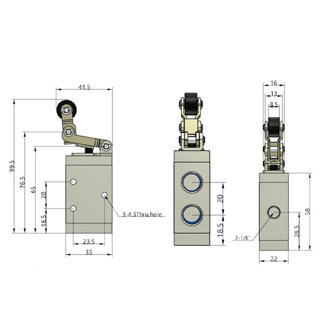
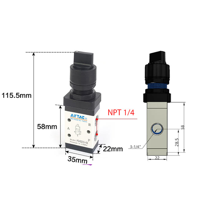
    Specifications: M3PL21008T is an AirTAC M3 control valve with 3 ports, 2 positions, a latching pushbutton with twist release actuator and NPT 1/4 inch connections. Code 210 selects the 200 series single-control body. The latching button is red, as specified for the blank color code. Product Catalog Download Airtac Product Catalog (PDF) For detailed product dimensions and mounting drawings, please download and refer to the PDF catalog. Functional Alternative Statement Airtac M3 series valves are functional alternatives to SMC VM400 series valves. Model Code Explained Parameter Details Exact ordering code M3PL21008T Series M3 3 ports, 2 positions; external direct mechanical control Control-head code PL Latching pushbutton with twist release Body code 210 = 200 series, single control Port-size code 08 NPT 1/4 inch Thread option T = NPT Blank color code Red latching button; the catalog lists no alternative PL color Technical Specifications Parameter Details Fluid Air, filtered through a 40 μm filter element Operating method External direct acting Valve function 3 ports, 2 positions Selected control form latching pushbutton with twist release Working connection NPT 1/4 inch Effective flow area 12.0 mm² Cv 0.67 Operating-pressure range 0–1.0 MPa (0–145 psi) Proof pressure 1.5 MPa (215 psi) Working temperature −20 to 70 °C Body material Aluminum alloy Lubrication Not required Features and Pneumatic Operation The sliding-column construction has internal sealing and a control force that the catalog states is unaffected by working pressure, with no back-pressure effect. The exhaust connections are placed above the body to make it easier to fit a suitable silencer and reduce exhaust noise and contamination; a silencer is not specified as included. The selected control head is manually operated. The available head forms serve different operator controls; only the head encoded in this exact model is selected here. Lubrication is not required. If lubricated air is introduced, continue using the same lubrication medium without interruption; the catalog recommends ISO VG32 oil or an equivalent grade. Port letters identify P as the supply, A as the controlled outlet and R as exhaust. The graphical symbol in the PDF defines the exact flow paths for the selected actuator and valve position. Selected Operating Travel Parameter Details Valve-spool stroke 2.0–3.3 mm Button / roller / handle stroke 5.9–7.2 mm The listed stroke ranges are installation limits for the selected control form. Travel is not an added body dimension. Use the drawing orientation and do not drive the mechanism past its stated range. Installation, Travel Limits and Operation Mount the valve through the body fixing points or use the illustrated panel arrangement where the selected head permits it. Keep the body and head aligned and retain access to the pneumatic ports. The catalog does not state a general screw-tightening torque. Do not exceed the selected spool and actuator stroke ranges. Excess travel imposed by the external mechanism can cause leakage or damage. Engineering-plastic button components must be operated by hand and must not be struck with metal tools; the dedicated mechanical roller/plunger models are actuated by their intended external mechanism. This latching control is manually reset by rotating the button after it has been pressed into the latched position. Body and Mounting Dimensions The M3 common-body table uses the basic B valve as its dimensional reference. The selected PL control head has its own drawing below; body and head references must not be added into an invented overall envelope. Drawing reference Value Drawing dimension A 35 mm Drawing dimension B 22 mm Drawing dimension C 64 mm Drawing dimension D 58 mm Drawing dimension K 4.3 mm Drawing dimension KA 23.5 mm Drawing dimension KB 18.5 mm Drawing dimension KC 20 mm Drawing dimension PA 20 mm Drawing dimension PB 18.5 mm Drawing dimension PC 28.5 mm Drawing P — three ports NPT 1/4 inch Body mounting holes 3 × Ø4.3 mm through-holes Selected Control Head and Replacement Reference The values below describe the selected actuator or control-head assembly. They are separate from the body drawing and must not be added indiscriminately to the body dimensions. Control-head drawing reference Value Head base width 36 mm Head base depth 30 mm Panel allowance reference 6 mm Panel mounting thread M22 × 1.25 Button diameter 36 mm Head height range in drawing 51.5–58.5 mm The M3 catalog explicitly lists control-head assembly S3PL05-P12A for this head family. The M3/S3 prefix on a shared replacement head is retained exactly; it does not change this valve’s M3 ordering code. This valve includes its selected actuator; a second head is not required for normal operation. Dimension Drawing Reminder All linear drawing values above are in millimeters unless a thread or angle unit is stated. The original drawings retain the dimension-arrow relationships, actuator orientations and port views that cannot be fully represented by a two-column table. For detailed product dimensions and mounting drawings, please download and refer to the PDF catalog. Internal Components — Catalog Reference The sectioned illustration is labeled M3R210. Its numbered components are listed below as a series construction reference. This is not a spare-parts kit or an assertion that every actuator variation has an identical exploded assembly. Materials are stated only where the catalog expressly supplies them. Drawing item Component 1 Bottom cover 2 Hex-socket screw 3 Spring 4 Spacer 5 Body 6 Cross-head screw 7 Roller holder 8 Roller 9 Rotating block 10 Axle 11 Cross-head screw 12 Front cover 13 Piston O-ring 14 Spool 15 Positioning block Flow Characteristics The catalog flow chart for M3B-210-08 plots operating pressure in MPa on the vertical axis from 0 to 1.0, and flow in L/min on the horizontal axis from 0 to 1300. The family of curves illustrates the pressure/flow relationship. Axis limits are graph bounds, not guaranteed rated flow values for this complete valve; use the supplied curve and the required pressure conditions. Supply Scope and Related Heads This ordering code identifies one valve with its selected control-head form. It does not encode a multiple-valve assembly, a spare head, a silencer, mounting-panel hardware or pneumatic tubing. Where the catalog lists a separately orderable head, its exact code is given above as a replacement reference; the source does not provide a screw/gasket quantity breakdown for a service kit. Series Ordering Options The M3 common range offers B, C, D, Y, R and L heads; red-only PL; and PP, PF, PM and HS in red, green or black. The 110 body uses 06 ports only; the 210 body offers 06 or 08. The separate 05 mini range has B, R and L heads only. Mini models do not use the 110/210 code or a PT/G/NPT suffix. For 1/8 and 1/4 inch connections, a blank thread suffix means PT, G means G thread and T means NPT. M5 connections have no such thread suffix. These are series alternatives; the selected configuration is the one decoded above. Reference Weight Catalog reference weight: 148 g, from the M3PL210 row of the 2022 comprehensive catalog weight table (paper page 300). The table distinguishes the selected series size and control-head type. Its reference does not separately list port, color or thread variants. The table states that weights are for reference only; actual weight is determined by the delivered product. This is not a measured or packaged shipping weight. Catalog Basis Technical information is taken from the linked M3 catalog and cross-checked against the 2022 comprehensive catalog, paper pages 143–145 (PDF pages 144–146). The paper-page-300 weight table is cited separately above. No unrelated series dimensions or weights are substituted. Optional Piping Accessories P = this M3 valve’s supply (NPT1/4); W = its controlled working port A (NPT1/4); E = its exhaust port R (NPT1/4). All three ports are female threaded connections. The drawing callout 3-P identifies three same-size ports; it does not mean three supply ports. Silencers serve E only; ASC and GAFR connect upstream of P only. Keep supply, working and exhaust circuits separate. No pilot or manifold route is assigned. Multiple keys retain each use. Tube OD is mm (in = inches); compression/tubing show OD × ID. These piping accessories are optional and ordered separately. Code-prefix uses (match the longest listed family prefix): ASC inline threaded flow control; GAFR upstream filter-regulator; NBB male–male; NBD male–female; NBESL adjustable silencer; NBKC compression fitting; NBPC metal straight; NBSL silencer; NBSLM miniature silencer; NPC straight; NPEB branch tee; NPED run tee; NPH banjo elbow; NPHF female branch banjo; NPHW twin banjo; NPKD reducing distribution fitting; NPL elbow; NPLL extended elbow; NPSA inline flow control; NPSS flow control; NPTL push-lock flow control; NPYB Y; NPZB cross. Use Size / complete codes P ASC20008T,GAFR20008ST,GAFR30008ST E,P,W (discontinued) male NPT1/2 ↔ male NPT1/4: NBB1/4-1/2male NPT1/4 ↔ male NPT1/4: NBB1/4-1/4male NPT3/8 ↔ male NPT1/4: NBB1/4-3/8male NPT1/8 ↔ male NPT1/4: NBB1/8-1/4male NPT1/4 ↔ female NPT1/8: NBD1/8-1/41/2 × 1/3 in: NBKC1/2-1/3-1/41/4 × 5/32 in: NBKC1/4-5/32-1/43/8 × 1/4 in: NBKC3/8-1/4-1/45/16 × 1/5 in: NBKC5/16-1/5-1/41/2 in: NBPC1/2-1/4,NPLL1/2-1/41/4 in: NBPC1/4-1/4,NPH1/4-1/4,NPHW1/4-1/4,NPLL1/4-1/4,NPSS1/4-1/4A,NPSS1/4-1/4B,NPZB1/4-1/43/8 in: NBPC3/8-1/4,NPH3/8-1/4,NPHW3/8-1/4,NPLL3/8-1/4,NPSS3/8-1/4A,NPSS3/8-1/4B,NPZB3/8-1/45/16 in: NBPC5/16-1/4,NPH5/16-1/4,NPHW5/16-1/4,NPLL5/16-1/4,NPSS5/16-1/4A,NPSS5/16-1/4B,NPZB5/16-1/41/4 in; male RA NPT1/4 / female RB NPT1/4: NPHF1/4-1/43/8 in; male RA NPT1/4 / female RB NPT1/4: NPHF3/8-1/45/16 in; male RA NPT1/4 / female RB NPT1/4: NPHF5/16-1/4main 5/16 / branch 1/4 in: NPKD5/16-1/4-1/4 E (discontinued) NBESL1/4 E NBSL1/4,NBSLM1/4 E,P,W 1/2 in: NPC1/2-1/4,NPEB1/2-1/4,NPED1/2-1/4,NPL1/2-1/4,NPSA1/2,NPYB1/2-1/41/4 in: NPC1/4-1/4,NPEB1/4-1/4,NPED1/4-1/4,NPL1/4-1/4,NPSA1/4,NPTL1/4-1/4A,NPTL1/4-1/4B,NPYB1/4-1/43/8 in: NPC3/8-1/4,NPEB3/8-1/4,NPED3/8-1/4,NPL3/8-1/4,NPSA3/8,NPTL3/8-1/4A,NPTL3/8-1/4B,NPYB3/8-1/45/16 in: NPC5/16-1/4,NPEB5/16-1/4,NPED5/16-1/4,NPL5/16-1/4,NPSA5/16,NPTL5/16-1/4A,NPTL5/16-1/4B,NPYB5/16-1/4 Match PT/G/NPT exactly. Use the specified thread seal or face gasket. Match tube OD and compression OD/ID; metric and inch sizes are not interchangeable. Use suitable soft nylon/PU tube and check seating, clearance, bends and flow. Tighten compression bodies by the hex, not tube nuts. Where listed: D is black, blank grey, -M miniature; -S denotes only the specified 304 stainless parts. NPSA are tube-side flow controls and need separate matching tube connections; they do not screw directly into P, W or E. NPHF use male RA at the valve; female RB requires its own matching male thread and seal and is not a tube socket. Match both adapter ends to their separate mating parts. Branches join one circuit. Keep supply P, working A and exhaust R separate; do not bridge these paths. Standard push-in fittings, silencers and flow-control parts: ≤1 MPa, −20–70°C. NBPC/compression fittings/thread adapters: ≤1 MPa. The listed metal push-in, compression and adapter groups have a 0–150°C range, limiting the connected valve path to 0–70°C or narrower. Apply every stricter component limit; no system vacuum rating is established. This mechanically or manually operated M3 valve operates at 0–1 MPa and −20–70°C with 40 µm filtered air. Accessory limits may narrow that range; proof pressure is not working pressure. The piping choices are optional and ordered separately, and do not establish separately orderable panel-mounting or internal-part kits. Flow-control suffix A restricts thread→tube, with free reverse flow; suffix B reverses it. Supply normally flows tube→thread and exhaust thread→tube. At valve working port A, suffix A restricts flow to the actuator and suffix B the return; cylinder-mounted orientation differs. Follow the flow symbols, including NPSA. Closed controls are not leak-tight isolation. Adjust gently without forcing stops; depressurize before tube removal. Never cap an active supply, working or exhaust connection. Silencers serve only exhaust R. Check flow capacity and back pressure, including adjustable silencers and remote exhaust lines; do not restrict the exhaust so that valve or actuator operation is impaired. ASC is a separately connected upstream supply flow control, assigned to P only. Both female ports require matching male connections; follow its P/A markings. Its limits are 0.05–0.95 MPa and −20–70°C with ≤40 µm filtration. The complete valve path must meet these and every stricter component limit; the valve’s 0–1 MPa range does not extend the ASC rating. GAFR is a separately connected upstream supply filter/regulator, assigned to P only. Both female ports require matching male piping; follow IN→OUT and check total flow and bowl/environment suitability. Inlet ≤1 MPa; regulation 0.15–0.9 MPa; −5–70°C, nonfreezing. Apply every stricter valve/component limit. Listed GAFR S versions have a 40 µm filter, PC bowl, differential/manual drain, bracket and round snap-in gauge (psi/bar), without a reverse-flow valve. Air lubrication is not required. If lubricated air is introduced, continue with consistent lubrication using ISO VG32 or equivalent oil. NPTL maximum cap-adjustment torque: 1/4: 0.16 N·m. These are not thread-installation torques. Items marked discontinued are historical service references, not current standard recommendations. Confirm availability or a manufacturer-approved replacement. An unmarked catalogue entry does not promise current production, stock or delivery. All listed options are ordered separately.
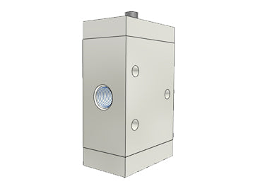
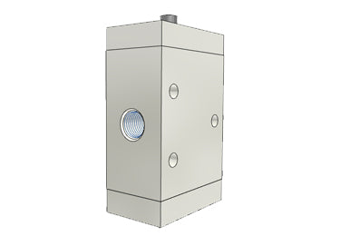
  • Airtac M3L210-06: Manual Valve. 3 Way - M3L21006 Airtac M3L210-06: Manual Valve. 3 Way - M3L21006 - 2

    Airtac M3 series: mechanically operated directional valve - M3L21006

    Specifications: M3L21006 is an AirTAC M3 control valve with 3 ports, 2 positions, a one-way roller lever with free return actuator and PT 1/8 inch connections. Code 210 selects the 200 series single-control body. Product Catalog Download Airtac Product Catalog (PDF) For detailed product dimensions and mounting drawings, please download and refer to the PDF catalog. Functional Alternative Statement Airtac M3 series valves are functional alternatives to SMC VM400 series valves. Model Code Explained Parameter Details Exact ordering code M3L21006 Series M3 3 ports, 2 positions; external direct mechanical control Control-head code L One-way roller lever with free return Body code 210 = 200 series, single control Port-size code 06 PT 1/8 inch Thread option Blank = PT Color suffix Not used for this control-head type Technical Specifications Parameter Details Fluid Air, filtered through a 40 μm filter element Operating method External direct acting Valve function 3 ports, 2 positions Selected control form one-way roller lever with free return Working connection PT 1/8 inch Effective flow area 9.0 mm² Cv 0.50 Operating-pressure range 0–1.0 MPa (0–145 psi) Proof pressure 1.5 MPa (215 psi) Working temperature −20 to 70 °C Body material Aluminum alloy Lubrication Not required Features and Pneumatic Operation The sliding-column construction has internal sealing and a control force that the catalog states is unaffected by working pressure, with no back-pressure effect. The exhaust connections are placed above the body to make it easier to fit a suitable silencer and reduce exhaust noise and contamination; a silencer is not specified as included. The operating force is supplied by an external machine mechanism. The catalog describes this arrangement for position detection or stroke/limit switching. The catalog identifies this control-head family as using a metal mechanism for durability and stable operation. That statement does not assign an unspecified material to every internal component. Lubrication is not required. If lubricated air is introduced, continue using the same lubrication medium without interruption; the catalog recommends ISO VG32 oil or an equivalent grade. Port letters identify P as the supply, A as the controlled outlet and R as exhaust. The graphical symbol in the PDF defines the exact flow paths for the selected actuator and valve position. Selected Operating Travel Parameter Details Valve-spool stroke 2.0–3.0 mm Button / roller / handle stroke 5.0–7.8 mm The listed stroke ranges are installation limits for the selected control form. Travel is not an added body dimension. Use the drawing orientation and do not drive the mechanism past its stated range. Installation, Travel Limits and Operation Mount the valve through the body fixing points or use the illustrated panel arrangement where the selected head permits it. Keep the body and head aligned and retain access to the pneumatic ports. The catalog does not state a general screw-tightening torque. Do not exceed the selected spool and actuator stroke ranges. Excess travel imposed by the external mechanism can cause leakage or damage. Engineering-plastic button components must be operated by hand and must not be struck with metal tools; the dedicated mechanical roller/plunger models are actuated by their intended external mechanism. The spring-return symbol and the installation notes identify an automatically returning actuation arrangement. Allow the actuator to return freely after releasing the operating force. The one-way roller lever switches when contacted from right to left in the catalog view. Motion from left to right is the free-return direction and does not switch the valve. Preserve the drawing orientation when applying this direction statement. Body and Mounting Dimensions The M3 common-body table uses the basic B valve as its dimensional reference. The selected L control head has its own drawing below; body and head references must not be added into an invented overall envelope. Drawing reference Value Drawing dimension A 35 mm Drawing dimension B 22 mm Drawing dimension C 64 mm Drawing dimension D 58 mm Drawing dimension K 4.3 mm Drawing dimension KA 23.5 mm Drawing dimension KB 18.5 mm Drawing dimension KC 20 mm Drawing dimension PA 20 mm Drawing dimension PB 18.5 mm Drawing dimension PC 28.5 mm Drawing P — three ports PT 1/8 inch Body mounting holes 3 × Ø4.3 mm through-holes Selected Control Head and Replacement Reference The values below describe the selected actuator or control-head assembly. They are separate from the body drawing and must not be added indiscriminately to the body dimensions. Control-head drawing reference Value Roller diameter 15 mm Head length reference 41.5 mm Longitudinal sub-span 32.5 mm Mounting longitudinal span 30.5 mm Head vertical reference 41.5 mm Vertical sub-span 18.5 mm Lower vertical reference 7 mm Head width reference 16 mm Inner width 8.5 mm Local width reference 13 mm The M3 catalog explicitly lists control-head assembly M3L210-P14A for this head family. The M3/S3 prefix on a shared replacement head is retained exactly; it does not change this valve’s M3 ordering code. This valve includes its selected actuator; a second head is not required for normal operation. Dimension Drawing Reminder All linear drawing values above are in millimeters unless a thread or angle unit is stated. The original drawings retain the dimension-arrow relationships, actuator orientations and port views that cannot be fully represented by a two-column table. For detailed product dimensions and mounting drawings, please download and refer to the PDF catalog. Internal Components — Catalog Reference The sectioned illustration is labeled M3R210. Its numbered components are listed below as a series construction reference. This is not a spare-parts kit or an assertion that every actuator variation has an identical exploded assembly. Materials are stated only where the catalog expressly supplies them. Drawing item Component 1 Bottom cover 2 Hex-socket screw 3 Spring 4 Spacer 5 Body 6 Cross-head screw 7 Roller holder 8 Roller 9 Rotating block 10 Axle 11 Cross-head screw 12 Front cover 13 Piston O-ring 14 Spool 15 Positioning block Flow Characteristics The catalog flow chart for M3B-210-06 plots operating pressure in MPa on the vertical axis from 0 to 1.0, and flow in L/min on the horizontal axis from 0 to 1200. The family of curves illustrates the pressure/flow relationship. Axis limits are graph bounds, not guaranteed rated flow values for this complete valve; use the supplied curve and the required pressure conditions. Supply Scope and Related Heads This ordering code identifies one valve with its selected control-head form. It does not encode a multiple-valve assembly, a spare head, a silencer, mounting-panel hardware or pneumatic tubing. Where the catalog lists a separately orderable head, its exact code is given above as a replacement reference; the source does not provide a screw/gasket quantity breakdown for a service kit. Series Ordering Options The M3 common range offers B, C, D, Y, R and L heads; red-only PL; and PP, PF, PM and HS in red, green or black. The 110 body uses 06 ports only; the 210 body offers 06 or 08. The separate 05 mini range has B, R and L heads only. Mini models do not use the 110/210 code or a PT/G/NPT suffix. For 1/8 and 1/4 inch connections, a blank thread suffix means PT, G means G thread and T means NPT. M5 connections have no such thread suffix. These are series alternatives; the selected configuration is the one decoded above. Reference Weight Catalog reference weight: 134 g, from the M3L210 row of the 2022 comprehensive catalog weight table (paper page 300). The table distinguishes the selected series size and control-head type. Its reference does not separately list port, color or thread variants. The table states that weights are for reference only; actual weight is determined by the delivered product. This is not a measured or packaged shipping weight. Catalog Basis Technical information is taken from the linked M3 catalog and cross-checked against the 2022 comprehensive catalog, paper pages 143–145 (PDF pages 144–146). The paper-page-300 weight table is cited separately above. No unrelated series dimensions or weights are substituted. Optional Piping Accessories P = this M3 valve’s supply (PT1/8); W = its controlled working port A (PT1/8); E = its exhaust port R (PT1/8). All three ports are female threaded connections. The drawing callout 3-P identifies three same-size ports; it does not mean three supply ports. Silencers serve E only; ASC and GAFR connect upstream of P only. Keep supply, working and exhaust circuits separate. No pilot or manifold route is assigned. Multiple keys retain each use. Tube OD is mm (in = inches); compression/tubing show OD × ID. These piping accessories are optional and ordered separately. Code-prefix uses (match the longest listed family prefix): ASC inline threaded flow control; BB male–male; BESL adjustable silencer; BKC compression fitting; BPC metal straight; BPOC metal straight; BSL silencer; BSLM miniature silencer; GAFR upstream filter-regulator; GPSA/PSA inline flow control; PAL plastic silencer; PALM miniature plastic silencer; PC straight; PEB branch tee; PED run tee; PH banjo elbow; PHF female branch banjo; PHW twin banjo; PKD reducing distribution fitting; PL elbow; PLL extended elbow; POC round straight; PPA plug-in silencer; PSL elbow flow control; PSS flow control; PTL push-lock flow control; PYB Y; PZB cross; UE PU tube; US PU tube. Use Size / complete codes P ASC10006,GAFR20006S E,P,W male PT1/8 ↔ male PT1/8: BB0101,BB0101-Smale PT1/4 ↔ male PT1/8: BB0102,BB0102-Smale PT3/8 ↔ male PT1/8: BB0103,BB0103-S4 × 2.5: BKC0425-01,BKC0425-01-S,UE95A040025100MBU,US98A040025100MBU6 × 4: BKC0604-01,BKC0604-01-S,UE95A060040100MBU,US98A060040100MBU8 × 5: BKC0805-01,BKC0805-01-S,UE95A080050100MBU,US98A080050100MBU8 × 5.5 or 6: BKC0806-01,BKC0806-01-S10: BPC1001,GPSA10,GPSA10D,PC1001,PC1001-S,PC1001D,PC1001D-S,PEB1001,PEB1001-S,PEB1001D,PEB1001D-S,PED1001,PED1001-S,PED1001D,PED1001D-S,PL1001,PL1001-S,PL1001D,PL1001D-S,PLL1001,PLL1001-S,PLL1001D,PLL1001D-S,POC1001,POC1001-S,POC1001D,POC1001D-S,PSA10,PSA10-S,PSA10D,PSA10D-S,PYB1001,PYB1001-S,PYB1001D,PYB1001D-S4: BPC401,BPOC401,GPSA4,GPSA4D,PC401,PC401-M,PC401-S,PC401D,PC401D-M,PC401D-S,PEB401,PEB401-S,PEB401D,PEB401D-S,PED401,PED401-S,PED401D,PED401D-S,PH401,PH401-S,PH401D,PH401D-S,PHW401,PHW401-S,PHW401D,PHW401D-S,PL401,PL401-M,PL401-S,PL401D,PL401D-M,PL401D-S,PLL401,PLL401-S,PLL401D,PLL401D-S,POC401,POC401-S,POC401D,POC401D-S,PSA4,PSA4-S,PSA4D,PSA4D-S,PSL401A,PSL401A-S,PSL401AD,PSL401AD-S,PSL401B,PSL401B-S,PSL401BD,PSL401BD-S,PTL401A-M,PTL401AD-M,PTL401B-M,PTL401BD-M,PYB401,PYB401-S,PYB401D,PYB401D-S6: BPC601,BPOC601,GPSA6,GPSA6D,PC601,PC601-M,PC601-S,PC601D,PC601D-M,PC601D-S,PEB601,PEB601-S,PEB601D,PEB601D-S,PED601,PED601-S,PED601D,PED601D-S,PH601,PH601-S,PH601D,PH601D-S,PHW601,PHW601-S,PHW601D,PHW601D-S,PL601,PL601-M,PL601-S,PL601D,PL601D-M,PL601D-S,PLL601,PLL601-S,PLL601D,PLL601D-S,POC601,POC601-S,POC601D,POC601D-S,PSA6,PSA6-S,PSA6D,PSA6D-S,PSL601A,PSL601A-S,PSL601AD,PSL601AD-S,PSL601B,PSL601B-S,PSL601BD,PSL601BD-S,PSS601A,PSS601A-S,PSS601AD,PSS601AD-S,PSS601B,PSS601B-S,PSS601BD,PSS601BD-S,PTL601A,PTL601A-M,PTL601AD,PTL601AD-M,PTL601B,PTL601B-M,PTL601BD,PTL601BD-M,PYB601,PYB601-S,PYB601D,PYB601D-S,PZB601,PZB601-S,PZB601D,PZB601D-S8: BPC801,BPOC801,GPSA8,GPSA8D,PC801,PC801-S,PC801D,PC801D-S,PEB801,PEB801-S,PEB801D,PEB801D-S,PED801,PED801-S,PED801D,PED801D-S,PH801,PH801-S,PH801D,PH801D-S,PHW801,PHW801-S,PHW801D,PHW801D-S,PL801,PL801-S,PL801D,PL801D-S,PLL801,PLL801-S,PLL801D,PLL801D-S,POC801,POC801-S,POC801D,POC801D-S,PSA8,PSA8-S,PSA8D,PSA8D-S,PSL801A,PSL801A-S,PSL801AD,PSL801AD-S,PSL801B,PSL801B-S,PSL801BD,PSL801BD-S,PSS801A,PSS801A-S,PSS801AD,PSS801AD-S,PSS801B,PSS801B-S,PSS801BD,PSS801BD-S,PTL801A,PTL801AD,PTL801B,PTL801BD,PYB801,PYB801-S,PYB801D,PYB801D-S,PZB801,PZB801-S,PZB801D,PZB801D-S12: GPSA12,GPSA12D,PC1201,PC1201-S,PC1201D,PC1201D-S,PL1201,PL1201-S,PL1201D,PL1201D-S,PSA12,PSA12-S,PSA12D,PSA12D-S4; male RA PT1/8 / female RB PT1/8: PHF401,PHF401-S,PHF401D,PHF401D-S6; male RA PT1/8 / female RB PT1/8: PHF601,PHF601-S,PHF601D,PHF601D-S8; male RA PT1/8 / female RB PT1/8: PHF801,PHF801-S,PHF801D,PHF801D-Smain 6 / branch 4: PKD6-401,PKD6-401-S,PKD6-401D,PKD6-401D-S10 × 6.5: UE95A100065100MBU,US98A100065100MBU12 × 8: UE95A120080100MBU,US98A120080100MBU E BESL01,BESL01-S,BSL01,BSL01-S,BSLM01,BSLM01-S,PAL01,PAL01D,PALM01,PALM01D10: PPA1012: PPA126: PPA68: PPA8 Match PT/G/NPT exactly. Use the specified thread seal or face gasket. Match tube OD and compression OD/ID; metric and inch sizes are not interchangeable. Use suitable soft nylon/PU tube and check seating, clearance, bends and flow. Tighten compression bodies by the hex, not tube nuts. Where listed: D is black, blank grey, -M miniature; -S denotes only the specified 304 stainless parts. PSA/GPSA are tube-side flow controls and need separate matching tube connections; they do not screw directly into P, W or E. PHF use male RA at the valve; female RB requires its own matching male thread and seal and is not a tube socket. Match both adapter ends to their separate mating parts. Branches join one circuit. Keep supply P, working A and exhaust R separate; do not bridge these paths. Standard push-in fittings, silencers and flow-control parts: ≤1 MPa, −20–70°C. Metal BPC/BPOC: ≤0.9 MPa; compression fittings/thread adapters: ≤1 MPa. The listed metal push-in, compression and adapter groups have a 0–150°C range, limiting the connected valve path to 0–70°C or narrower. Apply every stricter component limit; no system vacuum rating is established. This mechanically or manually operated M3 valve operates at 0–1 MPa and −20–70°C with 40 µm filtered air. Accessory limits may narrow that range; proof pressure is not working pressure. The piping choices are optional and ordered separately, and do not establish separately orderable panel-mounting or internal-part kits. Flow-control suffix A restricts thread→tube, with free reverse flow; suffix B reverses it. Supply normally flows tube→thread and exhaust thread→tube. At valve working port A, suffix A restricts flow to the actuator and suffix B the return; cylinder-mounted orientation differs. Follow the flow symbols, including PSA/GPSA. Closed controls are not leak-tight isolation. Adjust gently without forcing stops; depressurize before tube removal. Never cap an active supply, working or exhaust connection. Silencers serve only exhaust R. Check flow capacity and back pressure, including adjustable silencers and remote exhaust lines; do not restrict the exhaust so that valve or actuator operation is impaired. PPA silencers require matching metric push-in exhaust sockets; they are not threaded plugs or vacuum filters. ASC is a separately connected upstream supply flow control, assigned to P only. Both female ports require matching male connections; follow its P/A markings. Its limits are 0.05–0.95 MPa and −20–70°C with ≤40 µm filtration. The complete valve path must meet these and every stricter component limit; the valve’s 0–1 MPa range does not extend the ASC rating. GAFR is a separately connected upstream supply filter/regulator, assigned to P only. Both female ports require matching male piping; follow IN→OUT and check total flow and bowl/environment suitability. Inlet ≤1 MPa; regulation 0.15–0.9 MPa; −5–70°C, nonfreezing. Apply every stricter valve/component limit. Listed GAFR S versions have a 40 µm filter, PC bowl, differential/manual drain, bracket and round snap-in gauge (MPa/psi), without a reverse-flow valve. Air lubrication is not required. If lubricated air is introduced, continue with consistent lubrication using ISO VG32 or equivalent oil. US98A/UE95A examples are separately ordered blue 100 m metric PU coils rated 1 MPa at 23°C. US98A: −20–70°C; UE95A: −40–70°C. Match OD/ID and derate as temperature rises within valve/component limits; 1 MPa is not assured throughout. Use inch tube where the selected connection requires it; metric tube is not a substitute. PTL recommended cap-adjustment torque: 1/8: 0.08 N·m. These are not thread-installation torques. Items marked discontinued are historical service references, not current standard recommendations. Confirm availability or a manufacturer-approved replacement. An unmarked catalogue entry does not promise current production, stock or delivery. All listed options are ordered separately.
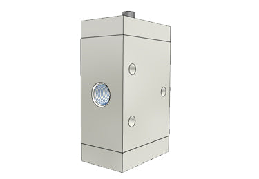
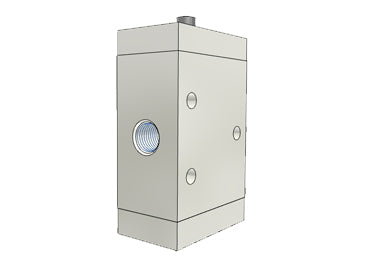
  • Airtac M3R-05: Manual Valve. 3 Way - M3R05 Airtac M3R-05: Manual Valve. 3 Way - M3R05 - 2

    Airtac M3 series: mechanically operated directional valve - M3R05

    Specifications: M3R05 is an AirTAC M3 control valve with 3 ports, 2 positions, a roller lever actuator and M5 × 0.8 connections. The 05 ending selects the dedicated M5 mini valve, without a 110/210 body code. Product Catalog Download Airtac Product Catalog (PDF) For detailed product dimensions and mounting drawings, please download and refer to the PDF catalog. Functional Alternative Statement Airtac M3 series valves are functional alternatives to SMC VM400 series valves. Model Code Explained Parameter Details Exact ordering code M3R05 Series M3 3 ports, 2 positions; external direct mechanical control Control-head code R Roller lever Body code Mini type without 110/210 size code Port-size code 05 M5 × 0.8 Thread option No thread suffix for the M5 × 0.8 port Color suffix Not used for this control-head type Technical Specifications Parameter Details Fluid Air, filtered through a 40 μm filter element Operating method External direct acting Valve function 3 ports, 2 positions Selected control form roller lever Working connection M5 × 0.8 Effective flow area 2.5 mm² Cv 0.14 Operating-pressure range 0–1.0 MPa (0–145 psi) Proof pressure 1.5 MPa (215 psi) Working temperature −20 to 70 °C Body material Aluminum alloy Lubrication Not required Features and Pneumatic Operation The sliding-column construction has internal sealing and a control force that the catalog states is unaffected by working pressure, with no back-pressure effect. The exhaust connections are placed above the body to make it easier to fit a suitable silencer and reduce exhaust noise and contamination; a silencer is not specified as included. The operating force is supplied by an external machine mechanism. The catalog describes this arrangement for position detection or stroke/limit switching. The catalog identifies this control-head family as using a metal mechanism for durability and stable operation. That statement does not assign an unspecified material to every internal component. Lubrication is not required. If lubricated air is introduced, continue using the same lubrication medium without interruption; the catalog recommends ISO VG32 oil or an equivalent grade. Port letters identify P as the supply, A as the controlled outlet and R as exhaust. The graphical symbol in the PDF defines the exact flow paths for the selected actuator and valve position. Selected Operating Travel Parameter Details Valve-spool stroke 2.0–3.0 mm Button / roller / handle stroke 6.0–8.5 mm The listed stroke ranges are installation limits for the selected control form. Travel is not an added body dimension. Use the drawing orientation and do not drive the mechanism past its stated range. Installation, Travel Limits and Operation Mount the valve through the body fixing points or use the illustrated panel arrangement where the selected head permits it. Keep the body and head aligned and retain access to the pneumatic ports. The catalog does not state a general screw-tightening torque. Do not exceed the selected spool and actuator stroke ranges. Excess travel imposed by the external mechanism can cause leakage or damage. Engineering-plastic button components must be operated by hand and must not be struck with metal tools; the dedicated mechanical roller/plunger models are actuated by their intended external mechanism. The spring-return symbol and the installation notes identify an automatically returning actuation arrangement. Allow the actuator to return freely after releasing the operating force. Body and Mounting Dimensions These are the dedicated M3 mini-body dimensions, not the 110 or 210 common-body dimensions. Drawing reference Value Body width 24 mm Body depth 13 mm Basic-body overall reference 41.3 mm Body vertical sub-span 35.7 mm Mounting horizontal reference 17 mm Mounting vertical sub-span 11 mm Lower mounting reference 12.4 mm Port vertical reference 10.5 mm Lower port reference 12.6 mm End reference 2 mm Mounting holes 3 × Ø3.3 mm through-holes Port callouts 3 × M5 × 0.8 Selected Control Head and Replacement Reference The values below describe the selected actuator or control-head assembly. They are separate from the body drawing and must not be added indiscriminately to the body dimensions. Control-head drawing reference Value Roller diameter 12 mm Head length reference 32 mm Longitudinal sub-span 25.5 mm Mounting longitudinal span 24 mm Head vertical reference 26 mm Vertical sub-span 18 mm Head width reference 14.5 mm Inner width 8.5 mm Local width reference 12 mm The M3 catalog explicitly lists control-head assembly M3R05-P14A for this head family. The M3/S3 prefix on a shared replacement head is retained exactly; it does not change this valve’s M3 ordering code. This valve includes its selected actuator; a second head is not required for normal operation. Dimension Drawing Reminder All linear drawing values above are in millimeters unless a thread or angle unit is stated. The original drawings retain the dimension-arrow relationships, actuator orientations and port views that cannot be fully represented by a two-column table. For detailed product dimensions and mounting drawings, please download and refer to the PDF catalog. Internal Components — Catalog Reference The sectioned illustration is labeled M3R210. Its numbered components are listed below as a series construction reference. This is not a spare-parts kit or an assertion that every actuator variation has an identical exploded assembly. Materials are stated only where the catalog expressly supplies them. Drawing item Component 1 Bottom cover 2 Hex-socket screw 3 Spring 4 Spacer 5 Body 6 Cross-head screw 7 Roller holder 8 Roller 9 Rotating block 10 Axle 11 Cross-head screw 12 Front cover 13 Piston O-ring 14 Spool 15 Positioning block Flow Characteristics The catalog flow chart for M3B-05 plots operating pressure in MPa on the vertical axis from 0 to 1.0, and flow in L/min on the horizontal axis from 0 to 350. The family of curves illustrates the pressure/flow relationship. Axis limits are graph bounds, not guaranteed rated flow values for this complete valve; use the supplied curve and the required pressure conditions. Supply Scope and Related Heads This ordering code identifies one valve with its selected control-head form. It does not encode a multiple-valve assembly, a spare head, a silencer, mounting-panel hardware or pneumatic tubing. Where the catalog lists a separately orderable head, its exact code is given above as a replacement reference; the source does not provide a screw/gasket quantity breakdown for a service kit. Series Ordering Options The M3 common range offers B, C, D, Y, R and L heads; red-only PL; and PP, PF, PM and HS in red, green or black. The 110 body uses 06 ports only; the 210 body offers 06 or 08. The separate 05 mini range has B, R and L heads only. Mini models do not use the 110/210 code or a PT/G/NPT suffix. For 1/8 and 1/4 inch connections, a blank thread suffix means PT, G means G thread and T means NPT. M5 connections have no such thread suffix. These are series alternatives; the selected configuration is the one decoded above. Reference Weight Catalog reference weight: 42 g, from the M3R05 row of the 2022 comprehensive catalog weight table (paper page 300). The table distinguishes the selected series size and control-head type. Its reference does not separately list port, color or thread variants. The table states that weights are for reference only; actual weight is determined by the delivered product. This is not a measured or packaged shipping weight. Catalog Basis Technical information is taken from the linked M3 catalog and cross-checked against the 2022 comprehensive catalog, paper pages 143–145 (PDF pages 144–146). The paper-page-300 weight table is cited separately above. No unrelated series dimensions or weights are substituted. Optional Piping Accessories P = this M3 valve’s supply (M5); W = its controlled working port A (M5); E = its exhaust port R (M5). All three ports are female threaded connections. The mini-body drawing identifies three M5 × 0.8 ports. Silencers serve E only. Keep supply, working and exhaust circuits separate. No pilot or manifold route is assigned. Multiple keys retain each use. Tube OD is mm (in = inches); compression/tubing show OD × ID. These piping accessories are optional and ordered separately. Code-prefix uses (match the longest listed family prefix): BKC/GBKC compression fitting; BPC/GBPC metal straight; BPOC metal straight; BSLM/GBSLM miniature silencer; GPC/PC straight; GPEB/PEB branch tee; GPED/PED run tee; GPH/PH banjo elbow; GPHF/PHF female branch banjo; GPL/PL elbow; GPLL/PLL extended elbow; GPSA/PSA inline flow control; GPSS/PSS flow control; GPYB/PYB Y; POC round straight; PPA plug-in silencer; PSL elbow flow control; PTL push-lock flow control; UE PU tube; US PU tube. Use Size / complete codes E,P,W 4 × 2.5: BKC0425-M5,BKC0425-M5-S,GBKC0425-M5,UE95A040025100MBU,US98A040025100MBU4: BPC4M5,BPOC4M5,GBPC4M5,GPC4M5-M,GPC4M5D-M,GPEB4M5,GPEB4M5D,GPED4M5,GPED4M5D,GPH4M5,GPH4M5D,GPHF4M5,GPHF4M5D,GPL4M5,GPL4M5-M,GPL4M5D,GPL4M5D-M,GPLL4M5,GPLL4M5D,GPSA4,GPSA4D,GPSS4M5A,GPSS4M5AD,GPSS4M5B,GPSS4M5BD,GPYB4M5,GPYB4M5D,PC4M5,PC4M5-M,PC4M5-S,PC4M5D,PC4M5D-M,PC4M5D-S,PEB4M5,PEB4M5-S,PEB4M5D,PEB4M5D-S,PED4M5,PED4M5-S,PED4M5D,PED4M5D-S,PH4M5,PH4M5-S,PH4M5D,PH4M5D-S,PHF4M5,PHF4M5-S,PHF4M5D,PHF4M5D-S,PL4M5,PL4M5-M,PL4M5-S,PL4M5D,PL4M5D-M,PL4M5D-S,PLL4M5,PLL4M5-S,PLL4M5D,PLL4M5D-S,POC4M5,POC4M5-S,POC4M5D,POC4M5D-S,PSA4,PSA4-S,PSA4D,PSA4D-S,PSL4M5A,PSL4M5A-S,PSL4M5AD,PSL4M5AD-S,PSL4M5B,PSL4M5B-S,PSL4M5BD,PSL4M5BD-S,PSS4M5A,PSS4M5A-S,PSS4M5AD,PSS4M5AD-S,PSS4M5B,PSS4M5B-S,PSS4M5BD,PSS4M5BD-S,PTL4M5A-M,PTL4M5AD-M,PTL4M5B-M,PTL4M5BD-M,PYB4M5,PYB4M5-S,PYB4M5D,PYB4M5D-S6: BPC6M5,BPOC6M5,GBPC6M5,GPC6M5,GPC6M5-M,GPC6M5D,GPC6M5D-M,GPEB6M5,GPEB6M5D,GPED6M5,GPED6M5D,GPH6M5,GPH6M5D,GPHF6M5,GPHF6M5D,GPL6M5,GPL6M5-M,GPL6M5D,GPL6M5D-M,GPLL6M5,GPLL6M5D,GPSA6,GPSA6D,GPYB6M5,GPYB6M5D,PC6M5,PC6M5-M,PC6M5-S,PC6M5D,PC6M5D-M,PC6M5D-S,PEB6M5,PEB6M5-S,PEB6M5D,PEB6M5D-S,PED6M5,PED6M5-S,PED6M5D,PED6M5D-S,PH6M5,PH6M5-S,PH6M5D,PH6M5D-S,PHF6M5,PHF6M5-S,PHF6M5D,PHF6M5D-S,PL6M5,PL6M5-M,PL6M5-S,PL6M5D,PL6M5D-M,PL6M5D-S,PLL6M5,PLL6M5-S,PLL6M5D,PLL6M5D-S,POC6M5,POC6M5-S,POC6M5D,POC6M5D-S,PSA6,PSA6-S,PSA6D,PSA6D-S,PSL6M5A,PSL6M5A-S,PSL6M5AD,PSL6M5AD-S,PSL6M5B,PSL6M5B-S,PSL6M5BD,PSL6M5BD-S,PTL6M5A-M,PTL6M5AD-M,PTL6M5B-M,PTL6M5BD-M,PYB6M5,PYB6M5-S,PYB6M5D,PYB6M5D-S3.2: GPC3.2M5-M,GPC3.2M5D-M,GPL3.2M5-M,GPL3.2M5D-M,PC3.2M5-M,PC3.2M5D-M,PL3.2M5-M,PL3.2M5D-M3.2 × 2: UE95A032020100MBU,US98A032020100MBU6 × 4: UE95A060040100MBU,US98A060040100MBU E BSLM5,BSLM5-S,BSLMM5,BSLMM5-S,GBSLM5,GBSLMM56: PPA6 Match PT/G/NPT exactly. M5, including G-prefixed M5, is M5 × 0.8, not #10-32UNF. Use the specified thread seal or face gasket. Match tube OD and compression OD/ID; metric and inch sizes are not interchangeable. Use suitable soft nylon/PU tube and check seating, clearance, bends and flow. Tighten compression bodies by the hex, not tube nuts. Where listed: D is black, blank grey, -M miniature; -S denotes only the specified 304 stainless parts. PSA/GPSA are tube-side flow controls and need separate matching tube connections; they do not screw directly into P, W or E. PHF/GPHF use male RA at the valve; female RB requires its own matching male thread and seal and is not a tube socket. Branches join one circuit. Keep supply P, working A and exhaust R separate; do not bridge these paths. Standard push-in fittings, silencers and flow-control parts: ≤1 MPa, −20–70°C. Metal BPC/BPOC/GBPC: ≤0.9 MPa; compression fittings: ≤1 MPa. The listed metal push-in and compression groups have a 0–150°C range, limiting the connected valve path to 0–70°C or narrower. Apply every stricter component limit; no system vacuum rating is established. This mechanically or manually operated M3 valve operates at 0–1 MPa and −20–70°C with 40 µm filtered air. Accessory limits may narrow that range; proof pressure is not working pressure. The piping choices are optional and ordered separately, and do not establish separately orderable panel-mounting or internal-part kits. Flow-control suffix A restricts thread→tube, with free reverse flow; suffix B reverses it. Supply normally flows tube→thread and exhaust thread→tube. At valve working port A, suffix A restricts flow to the actuator and suffix B the return; cylinder-mounted orientation differs. Follow the flow symbols, including PSA/GPSA. Closed controls are not leak-tight isolation. Adjust gently without forcing stops; depressurize before tube removal. Never cap an active supply, working or exhaust connection. Silencers serve only exhaust R. Check flow capacity and back pressure, including adjustable silencers and remote exhaust lines; do not restrict the exhaust so that valve or actuator operation is impaired. PPA silencers require matching metric push-in exhaust sockets; they are not threaded plugs or vacuum filters. US98A/UE95A examples are separately ordered blue 100 m metric PU coils rated 1 MPa at 23°C. US98A: −20–70°C; UE95A: −40–70°C. Match OD/ID and derate as temperature rises within valve/component limits; 1 MPa is not assured throughout. Use inch tube where the selected connection requires it; metric tube is not a substitute. PTL recommended cap-adjustment torque: miniature M5 PTL: 0.05 N·m. These are not thread-installation torques. Items marked discontinued are historical service references, not current standard recommendations. Confirm availability or a manufacturer-approved replacement. An unmarked catalogue entry does not promise current production, stock or delivery. All listed options are ordered separately.

  • Airtac M3PL110-06: Manual Valve. 3 Way - M3PL11006 Airtac M3PL110-06: Manual Valve. 3 Way - M3PL11006 - 2

    Airtac M3 series: manually operated directional valve - M3PL11006

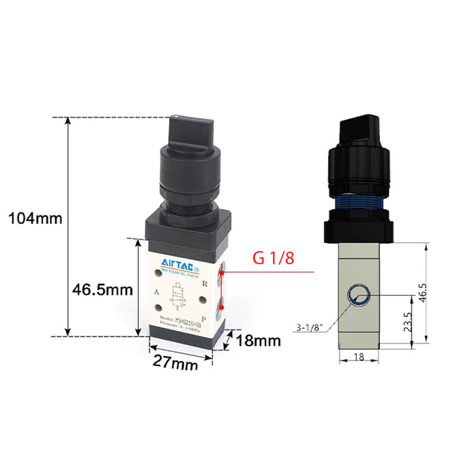
    Specifications: M3PL11006 is an AirTAC M3 control valve with 3 ports, 2 positions, a latching pushbutton with twist release actuator and PT 1/8 inch connections. Code 110 selects the 100 series single-control body. The latching button is red, as specified for the blank color code. Product Catalog Download Airtac Product Catalog (PDF) For detailed product dimensions and mounting drawings, please download and refer to the PDF catalog. Functional Alternative Statement Airtac M3 series valves are functional alternatives to SMC VM400 series valves. Model Code Explained Parameter Details Exact ordering code M3PL11006 Series M3 3 ports, 2 positions; external direct mechanical control Control-head code PL Latching pushbutton with twist release Body code 110 = 100 series, single control Port-size code 06 PT 1/8 inch Thread option Blank = PT Blank color code Red latching button; the catalog lists no alternative PL color Technical Specifications Parameter Details Fluid Air, filtered through a 40 μm filter element Operating method External direct acting Valve function 3 ports, 2 positions Selected control form latching pushbutton with twist release Working connection PT 1/8 inch Effective flow area 8.0 mm² Cv 0.45 Operating-pressure range 0–1.0 MPa (0–145 psi) Proof pressure 1.5 MPa (215 psi) Working temperature −20 to 70 °C Body material Aluminum alloy Lubrication Not required Features and Pneumatic Operation The sliding-column construction has internal sealing and a control force that the catalog states is unaffected by working pressure, with no back-pressure effect. The exhaust connections are placed above the body to make it easier to fit a suitable silencer and reduce exhaust noise and contamination; a silencer is not specified as included. The selected control head is manually operated. The available head forms serve different operator controls; only the head encoded in this exact model is selected here. Lubrication is not required. If lubricated air is introduced, continue using the same lubrication medium without interruption; the catalog recommends ISO VG32 oil or an equivalent grade. Port letters identify P as the supply, A as the controlled outlet and R as exhaust. The graphical symbol in the PDF defines the exact flow paths for the selected actuator and valve position. Selected Operating Travel Parameter Details Valve-spool stroke 2.0–3.3 mm Button / roller / handle stroke 5.9–7.2 mm The listed stroke ranges are installation limits for the selected control form. Travel is not an added body dimension. Use the drawing orientation and do not drive the mechanism past its stated range. Installation, Travel Limits and Operation Mount the valve through the body fixing points or use the illustrated panel arrangement where the selected head permits it. Keep the body and head aligned and retain access to the pneumatic ports. The catalog does not state a general screw-tightening torque. Do not exceed the selected spool and actuator stroke ranges. Excess travel imposed by the external mechanism can cause leakage or damage. Engineering-plastic button components must be operated by hand and must not be struck with metal tools; the dedicated mechanical roller/plunger models are actuated by their intended external mechanism. This latching control is manually reset by rotating the button after it has been pressed into the latched position. Body and Mounting Dimensions The M3 common-body table uses the basic B valve as its dimensional reference. The selected PL control head has its own drawing below; body and head references must not be added into an invented overall envelope. Drawing reference Value Drawing dimension A 27 mm Drawing dimension B 18 mm Drawing dimension C 52 mm Drawing dimension D 46.5 mm Drawing dimension K 3.3 mm Drawing dimension KA 18 mm Drawing dimension KB 15.5 mm Drawing dimension KC 16 mm Drawing dimension PA 16 mm Drawing dimension PB 15.5 mm Drawing dimension PC 23.5 mm Drawing P — three ports PT 1/8 inch Body mounting holes 3 × Ø3.3 mm through-holes Selected Control Head and Replacement Reference The values below describe the selected actuator or control-head assembly. They are separate from the body drawing and must not be added indiscriminately to the body dimensions. Control-head drawing reference Value Head base width 36 mm Head base depth 30 mm Panel allowance reference 6 mm Panel mounting thread M22 × 1.25 Button diameter 36 mm Head height range in drawing 51.5–58.5 mm The M3 catalog explicitly lists control-head assembly S3PL05-P12A for this head family. The M3/S3 prefix on a shared replacement head is retained exactly; it does not change this valve’s M3 ordering code. This valve includes its selected actuator; a second head is not required for normal operation. Dimension Drawing Reminder All linear drawing values above are in millimeters unless a thread or angle unit is stated. The original drawings retain the dimension-arrow relationships, actuator orientations and port views that cannot be fully represented by a two-column table. For detailed product dimensions and mounting drawings, please download and refer to the PDF catalog. Internal Components — Catalog Reference The sectioned illustration is labeled M3R210. Its numbered components are listed below as a series construction reference. This is not a spare-parts kit or an assertion that every actuator variation has an identical exploded assembly. Materials are stated only where the catalog expressly supplies them. Drawing item Component 1 Bottom cover 2 Hex-socket screw 3 Spring 4 Spacer 5 Body 6 Cross-head screw 7 Roller holder 8 Roller 9 Rotating block 10 Axle 11 Cross-head screw 12 Front cover 13 Piston O-ring 14 Spool 15 Positioning block Flow Characteristics The catalog flow chart for M3B-110-06 plots operating pressure in MPa on the vertical axis from 0 to 1.0, and flow in L/min on the horizontal axis from 0 to 1000. The family of curves illustrates the pressure/flow relationship. Axis limits are graph bounds, not guaranteed rated flow values for this complete valve; use the supplied curve and the required pressure conditions. Supply Scope and Related Heads This ordering code identifies one valve with its selected control-head form. It does not encode a multiple-valve assembly, a spare head, a silencer, mounting-panel hardware or pneumatic tubing. Where the catalog lists a separately orderable head, its exact code is given above as a replacement reference; the source does not provide a screw/gasket quantity breakdown for a service kit. Series Ordering Options The M3 common range offers B, C, D, Y, R and L heads; red-only PL; and PP, PF, PM and HS in red, green or black. The 110 body uses 06 ports only; the 210 body offers 06 or 08. The separate 05 mini range has B, R and L heads only. Mini models do not use the 110/210 code or a PT/G/NPT suffix. For 1/8 and 1/4 inch connections, a blank thread suffix means PT, G means G thread and T means NPT. M5 connections have no such thread suffix. These are series alternatives; the selected configuration is the one decoded above. Reference Weight Catalog reference weight: 94 g, from the M3PL110 row of the 2022 comprehensive catalog weight table (paper page 300). The table distinguishes the selected series size and control-head type. Its reference does not separately list port, color or thread variants. The table states that weights are for reference only; actual weight is determined by the delivered product. This is not a measured or packaged shipping weight. Catalog Basis Technical information is taken from the linked M3 catalog and cross-checked against the 2022 comprehensive catalog, paper pages 143–145 (PDF pages 144–146). The paper-page-300 weight table is cited separately above. No unrelated series dimensions or weights are substituted. Optional Piping Accessories P = this M3 valve’s supply (PT1/8); W = its controlled working port A (PT1/8); E = its exhaust port R (PT1/8). All three ports are female threaded connections. The drawing callout 3-P identifies three same-size ports; it does not mean three supply ports. Silencers serve E only; ASC and GAFR connect upstream of P only. Keep supply, working and exhaust circuits separate. No pilot or manifold route is assigned. Multiple keys retain each use. Tube OD is mm (in = inches); compression/tubing show OD × ID. These piping accessories are optional and ordered separately. Code-prefix uses (match the longest listed family prefix): ASC inline threaded flow control; BB male–male; BESL adjustable silencer; BKC compression fitting; BPC metal straight; BPOC metal straight; BSL silencer; BSLM miniature silencer; GAFR upstream filter-regulator; GPSA/PSA inline flow control; PAL plastic silencer; PALM miniature plastic silencer; PC straight; PEB branch tee; PED run tee; PH banjo elbow; PHF female branch banjo; PHW twin banjo; PKD reducing distribution fitting; PL elbow; PLL extended elbow; POC round straight; PPA plug-in silencer; PSL elbow flow control; PSS flow control; PTL push-lock flow control; PYB Y; PZB cross; UE PU tube; US PU tube. Use Size / complete codes P ASC10006,GAFR20006S E,P,W male PT1/8 ↔ male PT1/8: BB0101,BB0101-Smale PT1/4 ↔ male PT1/8: BB0102,BB0102-Smale PT3/8 ↔ male PT1/8: BB0103,BB0103-S4 × 2.5: BKC0425-01,BKC0425-01-S,UE95A040025100MBU,US98A040025100MBU6 × 4: BKC0604-01,BKC0604-01-S,UE95A060040100MBU,US98A060040100MBU8 × 5: BKC0805-01,BKC0805-01-S,UE95A080050100MBU,US98A080050100MBU8 × 5.5 or 6: BKC0806-01,BKC0806-01-S10: BPC1001,GPSA10,GPSA10D,PC1001,PC1001-S,PC1001D,PC1001D-S,PEB1001,PEB1001-S,PEB1001D,PEB1001D-S,PED1001,PED1001-S,PED1001D,PED1001D-S,PL1001,PL1001-S,PL1001D,PL1001D-S,PLL1001,PLL1001-S,PLL1001D,PLL1001D-S,POC1001,POC1001-S,POC1001D,POC1001D-S,PSA10,PSA10-S,PSA10D,PSA10D-S,PYB1001,PYB1001-S,PYB1001D,PYB1001D-S4: BPC401,BPOC401,GPSA4,GPSA4D,PC401,PC401-M,PC401-S,PC401D,PC401D-M,PC401D-S,PEB401,PEB401-S,PEB401D,PEB401D-S,PED401,PED401-S,PED401D,PED401D-S,PH401,PH401-S,PH401D,PH401D-S,PHW401,PHW401-S,PHW401D,PHW401D-S,PL401,PL401-M,PL401-S,PL401D,PL401D-M,PL401D-S,PLL401,PLL401-S,PLL401D,PLL401D-S,POC401,POC401-S,POC401D,POC401D-S,PSA4,PSA4-S,PSA4D,PSA4D-S,PSL401A,PSL401A-S,PSL401AD,PSL401AD-S,PSL401B,PSL401B-S,PSL401BD,PSL401BD-S,PTL401A-M,PTL401AD-M,PTL401B-M,PTL401BD-M,PYB401,PYB401-S,PYB401D,PYB401D-S6: BPC601,BPOC601,GPSA6,GPSA6D,PC601,PC601-M,PC601-S,PC601D,PC601D-M,PC601D-S,PEB601,PEB601-S,PEB601D,PEB601D-S,PED601,PED601-S,PED601D,PED601D-S,PH601,PH601-S,PH601D,PH601D-S,PHW601,PHW601-S,PHW601D,PHW601D-S,PL601,PL601-M,PL601-S,PL601D,PL601D-M,PL601D-S,PLL601,PLL601-S,PLL601D,PLL601D-S,POC601,POC601-S,POC601D,POC601D-S,PSA6,PSA6-S,PSA6D,PSA6D-S,PSL601A,PSL601A-S,PSL601AD,PSL601AD-S,PSL601B,PSL601B-S,PSL601BD,PSL601BD-S,PSS601A,PSS601A-S,PSS601AD,PSS601AD-S,PSS601B,PSS601B-S,PSS601BD,PSS601BD-S,PTL601A,PTL601A-M,PTL601AD,PTL601AD-M,PTL601B,PTL601B-M,PTL601BD,PTL601BD-M,PYB601,PYB601-S,PYB601D,PYB601D-S,PZB601,PZB601-S,PZB601D,PZB601D-S8: BPC801,BPOC801,GPSA8,GPSA8D,PC801,PC801-S,PC801D,PC801D-S,PEB801,PEB801-S,PEB801D,PEB801D-S,PED801,PED801-S,PED801D,PED801D-S,PH801,PH801-S,PH801D,PH801D-S,PHW801,PHW801-S,PHW801D,PHW801D-S,PL801,PL801-S,PL801D,PL801D-S,PLL801,PLL801-S,PLL801D,PLL801D-S,POC801,POC801-S,POC801D,POC801D-S,PSA8,PSA8-S,PSA8D,PSA8D-S,PSL801A,PSL801A-S,PSL801AD,PSL801AD-S,PSL801B,PSL801B-S,PSL801BD,PSL801BD-S,PSS801A,PSS801A-S,PSS801AD,PSS801AD-S,PSS801B,PSS801B-S,PSS801BD,PSS801BD-S,PTL801A,PTL801AD,PTL801B,PTL801BD,PYB801,PYB801-S,PYB801D,PYB801D-S,PZB801,PZB801-S,PZB801D,PZB801D-S12: GPSA12,GPSA12D,PC1201,PC1201-S,PC1201D,PC1201D-S,PL1201,PL1201-S,PL1201D,PL1201D-S,PSA12,PSA12-S,PSA12D,PSA12D-S4; male RA PT1/8 / female RB PT1/8: PHF401,PHF401-S,PHF401D,PHF401D-S6; male RA PT1/8 / female RB PT1/8: PHF601,PHF601-S,PHF601D,PHF601D-S8; male RA PT1/8 / female RB PT1/8: PHF801,PHF801-S,PHF801D,PHF801D-Smain 6 / branch 4: PKD6-401,PKD6-401-S,PKD6-401D,PKD6-401D-S10 × 6.5: UE95A100065100MBU,US98A100065100MBU12 × 8: UE95A120080100MBU,US98A120080100MBU E BESL01,BESL01-S,BSL01,BSL01-S,BSLM01,BSLM01-S,PAL01,PAL01D,PALM01,PALM01D10: PPA1012: PPA126: PPA68: PPA8 Match PT/G/NPT exactly. Use the specified thread seal or face gasket. Match tube OD and compression OD/ID; metric and inch sizes are not interchangeable. Use suitable soft nylon/PU tube and check seating, clearance, bends and flow. Tighten compression bodies by the hex, not tube nuts. Where listed: D is black, blank grey, -M miniature; -S denotes only the specified 304 stainless parts. PSA/GPSA are tube-side flow controls and need separate matching tube connections; they do not screw directly into P, W or E. PHF use male RA at the valve; female RB requires its own matching male thread and seal and is not a tube socket. Match both adapter ends to their separate mating parts. Branches join one circuit. Keep supply P, working A and exhaust R separate; do not bridge these paths. Standard push-in fittings, silencers and flow-control parts: ≤1 MPa, −20–70°C. Metal BPC/BPOC: ≤0.9 MPa; compression fittings/thread adapters: ≤1 MPa. The listed metal push-in, compression and adapter groups have a 0–150°C range, limiting the connected valve path to 0–70°C or narrower. Apply every stricter component limit; no system vacuum rating is established. This mechanically or manually operated M3 valve operates at 0–1 MPa and −20–70°C with 40 µm filtered air. Accessory limits may narrow that range; proof pressure is not working pressure. The piping choices are optional and ordered separately, and do not establish separately orderable panel-mounting or internal-part kits. Flow-control suffix A restricts thread→tube, with free reverse flow; suffix B reverses it. Supply normally flows tube→thread and exhaust thread→tube. At valve working port A, suffix A restricts flow to the actuator and suffix B the return; cylinder-mounted orientation differs. Follow the flow symbols, including PSA/GPSA. Closed controls are not leak-tight isolation. Adjust gently without forcing stops; depressurize before tube removal. Never cap an active supply, working or exhaust connection. Silencers serve only exhaust R. Check flow capacity and back pressure, including adjustable silencers and remote exhaust lines; do not restrict the exhaust so that valve or actuator operation is impaired. PPA silencers require matching metric push-in exhaust sockets; they are not threaded plugs or vacuum filters. ASC is a separately connected upstream supply flow control, assigned to P only. Both female ports require matching male connections; follow its P/A markings. Its limits are 0.05–0.95 MPa and −20–70°C with ≤40 µm filtration. The complete valve path must meet these and every stricter component limit; the valve’s 0–1 MPa range does not extend the ASC rating. GAFR is a separately connected upstream supply filter/regulator, assigned to P only. Both female ports require matching male piping; follow IN→OUT and check total flow and bowl/environment suitability. Inlet ≤1 MPa; regulation 0.15–0.9 MPa; −5–70°C, nonfreezing. Apply every stricter valve/component limit. Listed GAFR S versions have a 40 µm filter, PC bowl, differential/manual drain, bracket and round snap-in gauge (MPa/psi), without a reverse-flow valve. Air lubrication is not required. If lubricated air is introduced, continue with consistent lubrication using ISO VG32 or equivalent oil. US98A/UE95A examples are separately ordered blue 100 m metric PU coils rated 1 MPa at 23°C. US98A: −20–70°C; UE95A: −40–70°C. Match OD/ID and derate as temperature rises within valve/component limits; 1 MPa is not assured throughout. Use inch tube where the selected connection requires it; metric tube is not a substitute. PTL recommended cap-adjustment torque: 1/8: 0.08 N·m. These are not thread-installation torques. Items marked discontinued are historical service references, not current standard recommendations. Confirm availability or a manufacturer-approved replacement. An unmarked catalogue entry does not promise current production, stock or delivery. All listed options are ordered separately.

  • Airtac M3B210-08: Manual Valve. 3 Way - M3B21008 Airtac M3B210-08: Manual Valve. 3 Way - M3B21008 - 2

    Airtac M3 series: mechanically operated directional valve - M3B21008

    Specifications: M3B21008 is an AirTAC M3 control valve with 3 ports, 2 positions, a basic plunger actuator and PT 1/4 inch connections. Code 210 selects the 200 series single-control body. Product Catalog Download Airtac Product Catalog (PDF) For detailed product dimensions and mounting drawings, please download and refer to the PDF catalog. Functional Alternative Statement Airtac M3 series valves are functional alternatives to SMC VM400 series valves. Model Code Explained Parameter Details Exact ordering code M3B21008 Series M3 3 ports, 2 positions; external direct mechanical control Control-head code B Basic plunger Body code 210 = 200 series, single control Port-size code 08 PT 1/4 inch Thread option Blank = PT Color suffix Not used for this control-head type Technical Specifications Parameter Details Fluid Air, filtered through a 40 μm filter element Operating method External direct acting Valve function 3 ports, 2 positions Selected control form basic plunger Working connection PT 1/4 inch Effective flow area 12.0 mm² Cv 0.67 Operating-pressure range 0–1.0 MPa (0–145 psi) Proof pressure 1.5 MPa (215 psi) Working temperature −20 to 70 °C Body material Aluminum alloy Lubrication Not required Features and Pneumatic Operation The sliding-column construction has internal sealing and a control force that the catalog states is unaffected by working pressure, with no back-pressure effect. The exhaust connections are placed above the body to make it easier to fit a suitable silencer and reduce exhaust noise and contamination; a silencer is not specified as included. The operating force is supplied by an external machine mechanism. The catalog describes this arrangement for position detection or stroke/limit switching. Lubrication is not required. If lubricated air is introduced, continue using the same lubrication medium without interruption; the catalog recommends ISO VG32 oil or an equivalent grade. Port letters identify P as the supply, A as the controlled outlet and R as exhaust. The graphical symbol in the PDF defines the exact flow paths for the selected actuator and valve position. Selected Operating Travel Parameter Details Valve-spool stroke 2.0–3.3 mm Separate button / roller stroke Not separately stated for the basic plunger The listed stroke ranges are installation limits for the selected control form. Travel is not an added body dimension. Use the drawing orientation and do not drive the mechanism past its stated range. Installation, Travel Limits and Operation Mount the valve through the body fixing points or use the illustrated panel arrangement where the selected head permits it. Keep the body and head aligned and retain access to the pneumatic ports. The catalog does not state a general screw-tightening torque. Do not exceed the selected spool and actuator stroke ranges. Excess travel imposed by the external mechanism can cause leakage or damage. Engineering-plastic button components must be operated by hand and must not be struck with metal tools; the dedicated mechanical roller/plunger models are actuated by their intended external mechanism. The spring-return symbol and the installation notes identify an automatically returning actuation arrangement. Allow the actuator to return freely after releasing the operating force. Body and Mounting Dimensions The M3 common-body table uses the basic B valve as its dimensional reference. The selected B control head has its own drawing below; body and head references must not be added into an invented overall envelope. Drawing reference Value Drawing dimension A 35 mm Drawing dimension B 22 mm Drawing dimension C 64 mm Drawing dimension D 58 mm Drawing dimension K 4.3 mm Drawing dimension KA 23.5 mm Drawing dimension KB 18.5 mm Drawing dimension KC 20 mm Drawing dimension PA 20 mm Drawing dimension PB 18.5 mm Drawing dimension PC 28.5 mm Drawing P — three ports PT 1/4 inch Body mounting holes 3 × Ø4.3 mm through-holes Dimension Drawing Reminder All linear drawing values above are in millimeters unless a thread or angle unit is stated. The original drawings retain the dimension-arrow relationships, actuator orientations and port views that cannot be fully represented by a two-column table. For detailed product dimensions and mounting drawings, please download and refer to the PDF catalog. Internal Components — Catalog Reference The sectioned illustration is labeled M3R210. Its numbered components are listed below as a series construction reference. This is not a spare-parts kit or an assertion that every actuator variation has an identical exploded assembly. Materials are stated only where the catalog expressly supplies them. Drawing item Component 1 Bottom cover 2 Hex-socket screw 3 Spring 4 Spacer 5 Body 6 Cross-head screw 7 Roller holder 8 Roller 9 Rotating block 10 Axle 11 Cross-head screw 12 Front cover 13 Piston O-ring 14 Spool 15 Positioning block Flow Characteristics The catalog flow chart for M3B-210-08 plots operating pressure in MPa on the vertical axis from 0 to 1.0, and flow in L/min on the horizontal axis from 0 to 1300. The family of curves illustrates the pressure/flow relationship. Axis limits are graph bounds, not guaranteed rated flow values for this complete valve; use the supplied curve and the required pressure conditions. Supply Scope and Related Heads This ordering code identifies one valve with its selected control-head form. It does not encode a multiple-valve assembly, a spare head, a silencer, mounting-panel hardware or pneumatic tubing. Where the catalog lists a separately orderable head, its exact code is given above as a replacement reference; the source does not provide a screw/gasket quantity breakdown for a service kit. Series Ordering Options The M3 common range offers B, C, D, Y, R and L heads; red-only PL; and PP, PF, PM and HS in red, green or black. The 110 body uses 06 ports only; the 210 body offers 06 or 08. The separate 05 mini range has B, R and L heads only. Mini models do not use the 110/210 code or a PT/G/NPT suffix. For 1/8 and 1/4 inch connections, a blank thread suffix means PT, G means G thread and T means NPT. M5 connections have no such thread suffix. These are series alternatives; the selected configuration is the one decoded above. Reference Weight Catalog reference weight: 95 g, from the M3B210 row of the 2022 comprehensive catalog weight table (paper page 300). The table distinguishes the selected series size and control-head type. Its reference does not separately list port, color or thread variants. The table states that weights are for reference only; actual weight is determined by the delivered product. This is not a measured or packaged shipping weight. Catalog Basis Technical information is taken from the linked M3 catalog and cross-checked against the 2022 comprehensive catalog, paper pages 143–145 (PDF pages 144–146). The paper-page-300 weight table is cited separately above. No unrelated series dimensions or weights are substituted. Optional Piping Accessories P = this M3 valve’s supply (PT1/4); W = its controlled working port A (PT1/4); E = its exhaust port R (PT1/4). All three ports are female threaded connections. The drawing callout 3-P identifies three same-size ports; it does not mean three supply ports. Silencers serve E only; ASC and GAFR connect upstream of P only. Keep supply, working and exhaust circuits separate. No pilot or manifold route is assigned. Multiple keys retain each use. Tube OD is mm (in = inches); compression/tubing show OD × ID. These piping accessories are optional and ordered separately. Code-prefix uses (match the longest listed family prefix): ASC inline threaded flow control; BB male–male; BD male–female; BESL adjustable silencer; BKC compression fitting; BPC metal straight; BPOC metal straight; BSL silencer; BSLM miniature silencer; GAFR upstream filter-regulator; GPSA/PSA inline flow control; PAL plastic silencer; PALM miniature plastic silencer; PC straight; PEB branch tee; PED run tee; PH banjo elbow; PHF female branch banjo; PHW twin banjo; PKD reducing distribution fitting; PL elbow; PLL extended elbow; POC round straight; PPA plug-in silencer; PSL elbow flow control; PSS flow control; PTL push-lock flow control; PYB Y; PZB cross; UE PU tube; US PU tube. Use Size / complete codes P ASC20008,GAFR20008S,GAFR30008S E,P,W male PT1/4 ↔ male PT1/8: BB0102,BB0102-Smale PT1/4 ↔ male PT1/4: BB0202,BB0202-Smale PT3/8 ↔ male PT1/4: BB0203,BB0203-Smale PT1/2 ↔ male PT1/4: BB0204,BB0204-Smale PT1/4 ↔ female PT1/8: BD0102,BD0102-S6 × 4: BKC0604-02,BKC0604-02-S,UE95A060040100MBU,US98A060040100MBU8 × 5: BKC0805-02,BKC0805-02-S,UE95A080050100MBU,US98A080050100MBU8 × 5.5 or 6: BKC0806-02,BKC0806-02-S10 × 6.5: BKC1065-02,BKC1065-02-S,UE95A100065100MBU,US98A100065100MBU10 × 7.5 or 8: BKC1075-02,BKC1075-02-S12 × 8: BKC1208-02,BKC1208-02-S,UE95A120080100MBU,US98A120080100MBU12 × 9 or 10: BKC1209-02,BKC1209-02-S10: BPC1002,BPOC1002,GPSA10,GPSA10D,PC1002,PC1002-S,PC1002D,PC1002D-S,PEB1002,PEB1002-S,PEB1002D,PEB1002D-S,PED1002,PED1002-S,PED1002D,PED1002D-S,PH1002,PH1002-S,PH1002D,PH1002D-S,PHW1002,PHW1002-S,PHW1002D,PHW1002D-S,PL1002,PL1002-S,PL1002D,PL1002D-S,PLL1002,PLL1002-S,PLL1002D,PLL1002D-S,POC1002,POC1002-S,POC1002D,POC1002D-S,PSA10,PSA10-S,PSA10D,PSA10D-S,PSL1002A,PSL1002A-S,PSL1002AD,PSL1002AD-S,PSL1002B,PSL1002B-S,PSL1002BD,PSL1002BD-S,PSS1002A,PSS1002A-S,PSS1002AD,PSS1002AD-S,PSS1002B,PSS1002B-S,PSS1002BD,PSS1002BD-S,PTL1002A,PTL1002AD,PTL1002B,PTL1002BD,PYB1002,PYB1002-S,PYB1002D,PYB1002D-S,PZB1002,PZB1002-S,PZB1002D,PZB1002D-S12: BPC1202,GPSA12,GPSA12D,PC1202,PC1202-S,PC1202D,PC1202D-S,PEB1202,PEB1202-S,PEB1202D,PEB1202D-S,PED1202,PED1202-S,PED1202D,PED1202D-S,PL1202,PL1202-S,PL1202D,PL1202D-S,PLL1202,PLL1202-S,PLL1202D,PLL1202D-S,POC1202,POC1202-S,POC1202D,POC1202D-S,PSA12,PSA12-S,PSA12D,PSA12D-S,PYB1202,PYB1202-S,PYB1202D,PYB1202D-S4: BPC402,GPSA4,GPSA4D,PC402,PC402-S,PC402D,PC402D-S,PEB402,PEB402-S,PEB402D,PEB402D-S,PED402,PED402-S,PED402D,PED402D-S,PL402,PL402-S,PL402D,PL402D-S,PLL402,PLL402-S,PLL402D,PLL402D-S,POC402,POC402-S,POC402D,POC402D-S,PSA4,PSA4-S,PSA4D,PSA4D-S,PYB402,PYB402-S,PYB402D,PYB402D-S6: BPC602,BPOC602,GPSA6,GPSA6D,PC602,PC602-S,PC602D,PC602D-S,PEB602,PEB602-S,PEB602D,PEB602D-S,PED602,PED602-S,PED602D,PED602D-S,PH602,PH602-S,PH602D,PH602D-S,PHW602,PHW602-S,PHW602D,PHW602D-S,PL602,PL602-S,PL602D,PL602D-S,PLL602,PLL602-S,PLL602D,PLL602D-S,POC602,POC602-S,POC602D,POC602D-S,PSA6,PSA6-S,PSA6D,PSA6D-S,PSL602A,PSL602A-S,PSL602AD,PSL602AD-S,PSL602B,PSL602B-S,PSL602BD,PSL602BD-S,PSS602A,PSS602A-S,PSS602AD,PSS602AD-S,PSS602B,PSS602B-S,PSS602BD,PSS602BD-S,PTL602A,PTL602AD,PTL602B,PTL602BD,PYB602,PYB602-S,PYB602D,PYB602D-S,PZB602,PZB602-S,PZB602D,PZB602D-S8: BPC802,BPOC802,GPSA8,GPSA8D,PC802,PC802-S,PC802D,PC802D-S,PEB802,PEB802-S,PEB802D,PEB802D-S,PED802,PED802-S,PED802D,PED802D-S,PH802,PH802-S,PH802D,PH802D-S,PHW802,PHW802-S,PHW802D,PHW802D-S,PL802,PL802-S,PL802D,PL802D-S,PLL802,PLL802-S,PLL802D,PLL802D-S,POC802,POC802-S,POC802D,POC802D-S,PSA8,PSA8-S,PSA8D,PSA8D-S,PSL802A,PSL802A-S,PSL802AD,PSL802AD-S,PSL802B,PSL802B-S,PSL802BD,PSL802BD-S,PSS802A,PSS802A-S,PSS802AD,PSS802AD-S,PSS802B,PSS802B-S,PSS802BD,PSS802BD-S,PTL802A,PTL802AD,PTL802B,PTL802BD,PYB802,PYB802-S,PYB802D,PYB802D-S,PZB802,PZB802-S,PZB802D,PZB802D-S10; male RA PT1/4 / female RB PT1/4: PHF1002,PHF1002-S,PHF1002D,PHF1002D-S6; male RA PT1/4 / female RB PT1/4: PHF602,PHF602-S,PHF602D,PHF602D-S8; male RA PT1/4 / female RB PT1/4: PHF802,PHF802-S,PHF802D,PHF802D-Smain 8 / branch 6: PKD8-602,PKD8-602-S,PKD8-602D,PKD8-602D-S4 × 2.5: UE95A040025100MBU,US98A040025100MBU E BESL02,BESL02-S,BSL02,BSL02-S,BSLM02,BSLM02-S,PAL02,PAL02D,PALM02,PALM02D10: PPA1012: PPA126: PPA68: PPA8 Match PT/G/NPT exactly. Use the specified thread seal or face gasket. Match tube OD and compression OD/ID; metric and inch sizes are not interchangeable. Use suitable soft nylon/PU tube and check seating, clearance, bends and flow. Tighten compression bodies by the hex, not tube nuts. Where listed: D is black, blank grey, -M miniature; -S denotes only the specified 304 stainless parts. PSA/GPSA are tube-side flow controls and need separate matching tube connections; they do not screw directly into P, W or E. PHF use male RA at the valve; female RB requires its own matching male thread and seal and is not a tube socket. Match both adapter ends to their separate mating parts. Branches join one circuit. Keep supply P, working A and exhaust R separate; do not bridge these paths. Standard push-in fittings, silencers and flow-control parts: ≤1 MPa, −20–70°C. Metal BPC/BPOC: ≤0.9 MPa; compression fittings/thread adapters: ≤1 MPa. The listed metal push-in, compression and adapter groups have a 0–150°C range, limiting the connected valve path to 0–70°C or narrower. Apply every stricter component limit; no system vacuum rating is established. This mechanically or manually operated M3 valve operates at 0–1 MPa and −20–70°C with 40 µm filtered air. Accessory limits may narrow that range; proof pressure is not working pressure. The piping choices are optional and ordered separately, and do not establish separately orderable panel-mounting or internal-part kits. Flow-control suffix A restricts thread→tube, with free reverse flow; suffix B reverses it. Supply normally flows tube→thread and exhaust thread→tube. At valve working port A, suffix A restricts flow to the actuator and suffix B the return; cylinder-mounted orientation differs. Follow the flow symbols, including PSA/GPSA. Closed controls are not leak-tight isolation. Adjust gently without forcing stops; depressurize before tube removal. Never cap an active supply, working or exhaust connection. Silencers serve only exhaust R. Check flow capacity and back pressure, including adjustable silencers and remote exhaust lines; do not restrict the exhaust so that valve or actuator operation is impaired. PPA silencers require matching metric push-in exhaust sockets; they are not threaded plugs or vacuum filters. ASC is a separately connected upstream supply flow control, assigned to P only. Both female ports require matching male connections; follow its P/A markings. Its limits are 0.05–0.95 MPa and −20–70°C with ≤40 µm filtration. The complete valve path must meet these and every stricter component limit; the valve’s 0–1 MPa range does not extend the ASC rating. GAFR is a separately connected upstream supply filter/regulator, assigned to P only. Both female ports require matching male piping; follow IN→OUT and check total flow and bowl/environment suitability. Inlet ≤1 MPa; regulation 0.15–0.9 MPa; −5–70°C, nonfreezing. Apply every stricter valve/component limit. Listed GAFR S versions have a 40 µm filter, PC bowl, differential/manual drain, bracket and round snap-in gauge (MPa/psi), without a reverse-flow valve. Air lubrication is not required. If lubricated air is introduced, continue with consistent lubrication using ISO VG32 or equivalent oil. US98A/UE95A examples are separately ordered blue 100 m metric PU coils rated 1 MPa at 23°C. US98A: −20–70°C; UE95A: −40–70°C. Match OD/ID and derate as temperature rises within valve/component limits; 1 MPa is not assured throughout. Use inch tube where the selected connection requires it; metric tube is not a substitute. PTL recommended cap-adjustment torque: 1/4: 0.16 N·m. These are not thread-installation torques. Items marked discontinued are historical service references, not current standard recommendations. Confirm availability or a manufacturer-approved replacement. An unmarked catalogue entry does not promise current production, stock or delivery. All listed options are ordered separately.

  • Airtac M3HS110-06: Manual Valve. 3 Way - M3HS11006BG Airtac M3HS110-06: Manual Valve. 3 Way - M3HS11006BG - 2

    Airtac M3 series: manually operated directional valve - M3HS11006BG

    Specifications: M3HS11006BG is an AirTAC M3 control valve with 3 ports, 2 positions, a selector actuator and G 1/8 inch connections. Code 110 selects the 100 series single-control body. Button/selector color B is black. Product Catalog Download Airtac Product Catalog (PDF) For detailed product dimensions and mounting drawings, please download and refer to the PDF catalog. Functional Alternative Statement Airtac M3 series valves are functional alternatives to SMC VM400 series valves. Model Code Explained Parameter Details Exact ordering code M3HS11006BG Series M3 3 ports, 2 positions; external direct mechanical control Control-head code HS Selector Body code 110 = 100 series, single control Port-size code 06 G 1/8 inch Thread option G = G Color code B Black Technical Specifications Parameter Details Fluid Air, filtered through a 40 μm filter element Operating method External direct acting Valve function 3 ports, 2 positions Selected control form selector Working connection G 1/8 inch Effective flow area 8.0 mm² Cv 0.45 Operating-pressure range 0–1.0 MPa (0–145 psi) Proof pressure 1.5 MPa (215 psi) Working temperature −20 to 70 °C Body material Aluminum alloy Lubrication Not required Features and Pneumatic Operation The sliding-column construction has internal sealing and a control force that the catalog states is unaffected by working pressure, with no back-pressure effect. The exhaust connections are placed above the body to make it easier to fit a suitable silencer and reduce exhaust noise and contamination; a silencer is not specified as included. The selected control head is manually operated. The available head forms serve different operator controls; only the head encoded in this exact model is selected here. Lubrication is not required. If lubricated air is introduced, continue using the same lubrication medium without interruption; the catalog recommends ISO VG32 oil or an equivalent grade. Port letters identify P as the supply, A as the controlled outlet and R as exhaust. The graphical symbol in the PDF defines the exact flow paths for the selected actuator and valve position. Selected Operating Travel Parameter Details Valve-spool stroke 2.0–3.3 mm Button / roller / handle stroke 5.1–6.4 mm The listed stroke ranges are installation limits for the selected control form. Travel is not an added body dimension. Use the drawing orientation and do not drive the mechanism past its stated range. Installation, Travel Limits and Operation Mount the valve through the body fixing points or use the illustrated panel arrangement where the selected head permits it. Keep the body and head aligned and retain access to the pneumatic ports. The catalog does not state a general screw-tightening torque. Do not exceed the selected spool and actuator stroke ranges. Excess travel imposed by the external mechanism can cause leakage or damage. Engineering-plastic button components must be operated by hand and must not be struck with metal tools; the dedicated mechanical roller/plunger models are actuated by their intended external mechanism. This control form is manually reset. Return the lever or selector deliberately to the required position; it is not described as an automatically returning pushbutton. Body and Mounting Dimensions The M3 common-body table uses the basic B valve as its dimensional reference. The selected HS control head has its own drawing below; body and head references must not be added into an invented overall envelope. Drawing reference Value Drawing dimension A 27 mm Drawing dimension B 18 mm Drawing dimension C 52 mm Drawing dimension D 46.5 mm Drawing dimension K 3.3 mm Drawing dimension KA 18 mm Drawing dimension KB 15.5 mm Drawing dimension KC 16 mm Drawing dimension PA 16 mm Drawing dimension PB 15.5 mm Drawing dimension PC 23.5 mm Drawing P — three ports G 1/8 inch Body mounting holes 3 × Ø3.3 mm through-holes Selected Control Head and Replacement Reference The values below describe the selected actuator or control-head assembly. They are separate from the body drawing and must not be added indiscriminately to the body dimensions. Control-head drawing reference Value Head base width 36 mm Head base depth 30 mm Panel allowance reference 6 mm Panel mounting thread M22 × 1.25 Button / selector diameter 28.5 mm Head height reference 57.5 mm The M3 catalog explicitly lists control-head assembly S3HS05-P13A for this head family. The M3/S3 prefix on a shared replacement head is retained exactly; it does not change this valve’s M3 ordering code. This valve includes its selected actuator; a second head is not required for normal operation. Dimension Drawing Reminder All linear drawing values above are in millimeters unless a thread or angle unit is stated. The original drawings retain the dimension-arrow relationships, actuator orientations and port views that cannot be fully represented by a two-column table. For detailed product dimensions and mounting drawings, please download and refer to the PDF catalog. Internal Components — Catalog Reference The sectioned illustration is labeled M3R210. Its numbered components are listed below as a series construction reference. This is not a spare-parts kit or an assertion that every actuator variation has an identical exploded assembly. Materials are stated only where the catalog expressly supplies them. Drawing item Component 1 Bottom cover 2 Hex-socket screw 3 Spring 4 Spacer 5 Body 6 Cross-head screw 7 Roller holder 8 Roller 9 Rotating block 10 Axle 11 Cross-head screw 12 Front cover 13 Piston O-ring 14 Spool 15 Positioning block Flow Characteristics The catalog flow chart for M3B-110-06 plots operating pressure in MPa on the vertical axis from 0 to 1.0, and flow in L/min on the horizontal axis from 0 to 1000. The family of curves illustrates the pressure/flow relationship. Axis limits are graph bounds, not guaranteed rated flow values for this complete valve; use the supplied curve and the required pressure conditions. Supply Scope and Related Heads This ordering code identifies one valve with its selected control-head form. It does not encode a multiple-valve assembly, a spare head, a silencer, mounting-panel hardware or pneumatic tubing. Where the catalog lists a separately orderable head, its exact code is given above as a replacement reference; the source does not provide a screw/gasket quantity breakdown for a service kit. Series Ordering Options The M3 common range offers B, C, D, Y, R and L heads; red-only PL; and PP, PF, PM and HS in red, green or black. The 110 body uses 06 ports only; the 210 body offers 06 or 08. The separate 05 mini range has B, R and L heads only. Mini models do not use the 110/210 code or a PT/G/NPT suffix. For 1/8 and 1/4 inch connections, a blank thread suffix means PT, G means G thread and T means NPT. M5 connections have no such thread suffix. These are series alternatives; the selected configuration is the one decoded above. Reference Weight Catalog reference weight: 83 g, from the M3HS110 row of the 2022 comprehensive catalog weight table (paper page 300). The table distinguishes the selected series size and control-head type. Its reference does not separately list port, color or thread variants. The table states that weights are for reference only; actual weight is determined by the delivered product. This is not a measured or packaged shipping weight. Catalog Basis Technical information is taken from the linked M3 catalog and cross-checked against the 2022 comprehensive catalog, paper pages 143–145 (PDF pages 144–146). The paper-page-300 weight table is cited separately above. No unrelated series dimensions or weights are substituted. Matching Accessory Codes and Conditions Item Complete codes and use HS replacement heads (green/red/black) These are optional replacement selector heads for the corresponding M3 HS common 110/210 valve families. Replacement-head suffixes -P11A, -P12A and -P13A mean green, red and black, respectively. The valve already includes its selected black head; order a spare separately only when needed. Retain the selected head form and follow the operating-travel, reset and mounting instructions above. The S3 prefix is the catalogue shared-head code, not a complete valve.S3HS05-P11A,S3HS05-P12A Optional Piping Accessories P = this M3 valve’s supply (G1/8); W = its controlled working port A (G1/8); E = its exhaust port R (G1/8). All three ports are female threaded connections. The drawing callout 3-P identifies three same-size ports; it does not mean three supply ports. Silencers serve E only; ASC and GAFR connect upstream of P only. Keep supply, working and exhaust circuits separate. No pilot or manifold route is assigned. Multiple keys retain each use. Tube OD is mm (in = inches); compression/tubing show OD × ID. These piping accessories are optional and ordered separately. Code-prefix uses (match the longest listed family prefix): ASC inline threaded flow control; GAFR upstream filter-regulator; GBB male–male; GBESL adjustable silencer; GBKC compression fitting; GBPC metal straight; GBSL silencer; GBSLM miniature silencer; GPC straight; GPEB branch tee; GPED run tee; GPH banjo elbow; GPHF female branch banjo; GPHW twin banjo; GPKD reducing distribution fitting; GPL elbow; GPLL extended elbow; GPSA/PSA inline flow control; GPSS flow control; GPTL push-lock flow control; GPYB Y; GPZB cross; PPA plug-in silencer; UE PU tube; US PU tube. Use Size / complete codes P ASC10006G,GAFR20006SG E,P,W male G1/8 ↔ male G1/8: GBB0101male G1/4 ↔ male G1/8: GBB0102male G3/8 ↔ male G1/8: GBB01034 × 2.5: GBKC0425-01,UE95A040025100MBU,US98A040025100MBU6 × 4: GBKC0604-01,UE95A060040100MBU,US98A060040100MBU8 × 5: GBKC0805-01,UE95A080050100MBU,US98A080050100MBU8 × 5.5 or 6: GBKC0806-0110: GBPC1001,GPC1001,GPC1001D,GPEB1001,GPEB1001D,GPED1001,GPED1001D,GPL1001,GPL1001D,GPLL1001,GPLL1001D,GPSA10,GPSA10D,GPYB1001,GPYB1001D,PSA10,PSA10-S,PSA10D,PSA10D-S4: GBPC401,GPC401-M,GPC401D-M,GPEB401,GPEB401D,GPED401,GPED401D,GPH401,GPH401D,GPHW401,GPHW401D,GPL401-M,GPL401D-M,GPLL401,GPLL401D,GPSA4,GPSA4D,GPYB401,GPYB401D,PSA4,PSA4-S,PSA4D,PSA4D-S6: GBPC601,GPC601,GPC601-M,GPC601D,GPC601D-M,GPEB601,GPEB601D,GPED601,GPED601D,GPH601,GPH601D,GPHW601,GPHW601D,GPL601,GPL601-M,GPL601D,GPL601D-M,GPLL601,GPLL601D,GPSA6,GPSA6D,GPSS601A,GPSS601AD,GPSS601B,GPSS601BD,GPTL601A,GPTL601AD,GPTL601B,GPTL601BD,GPYB601,GPYB601D,GPZB601,GPZB601D,PSA6,PSA6-S,PSA6D,PSA6D-S8: GBPC801,GPC801,GPC801D,GPEB801,GPEB801D,GPED801,GPED801D,GPH801,GPH801D,GPHW801,GPHW801D,GPL801,GPL801D,GPLL801,GPLL801D,GPSA8,GPSA8D,GPSS801A,GPSS801AD,GPSS801B,GPSS801BD,GPTL801A,GPTL801AD,GPTL801B,GPTL801BD,GPYB801,GPYB801D,GPZB801,GPZB801D,PSA8,PSA8-S,PSA8D,PSA8D-S12: GPC1201,GPC1201D,GPL1201,GPL1201D,GPSA12,GPSA12D,PSA12,PSA12-S,PSA12D,PSA12D-S4; male RA G1/8 / female RB G1/8: GPHF401,GPHF401D6; male RA G1/8 / female RB G1/8: GPHF601,GPHF601D8; male RA G1/8 / female RB G1/8: GPHF801,GPHF801Dmain 6 / branch 4: GPKD6-401,GPKD6-401D10 × 6.5: UE95A100065100MBU,US98A100065100MBU12 × 8: UE95A120080100MBU,US98A120080100MBU E GBESL01,GBSL01,GBSLM0110: PPA1012: PPA126: PPA68: PPA8 Match PT/G/NPT exactly. Use the specified thread seal or face gasket. Match tube OD and compression OD/ID; metric and inch sizes are not interchangeable. Use suitable soft nylon/PU tube and check seating, clearance, bends and flow. Tighten compression bodies by the hex, not tube nuts. Where listed: D is black, blank grey, -M miniature; -S denotes only the specified 304 stainless parts. PSA/GPSA are tube-side flow controls and need separate matching tube connections; they do not screw directly into P, W or E. GPHF use male RA at the valve; female RB requires its own matching male thread and seal and is not a tube socket. Match both adapter ends to their separate mating parts. Branches join one circuit. Keep supply P, working A and exhaust R separate; do not bridge these paths. Standard push-in fittings, silencers and flow-control parts: ≤1 MPa, −20–70°C. Metal GBPC: ≤0.9 MPa; compression fittings/thread adapters: ≤1 MPa. The listed metal push-in, compression and adapter groups have a 0–150°C range, limiting the connected valve path to 0–70°C or narrower. Apply every stricter component limit; no system vacuum rating is established. This mechanically or manually operated M3 valve operates at 0–1 MPa and −20–70°C with 40 µm filtered air. Accessory limits may narrow that range; proof pressure is not working pressure. The piping choices are optional and ordered separately, and do not establish separately orderable panel-mounting or internal-part kits. Flow-control suffix A restricts thread→tube, with free reverse flow; suffix B reverses it. Supply normally flows tube→thread and exhaust thread→tube. At valve working port A, suffix A restricts flow to the actuator and suffix B the return; cylinder-mounted orientation differs. Follow the flow symbols, including PSA/GPSA. Closed controls are not leak-tight isolation. Adjust gently without forcing stops; depressurize before tube removal. Never cap an active supply, working or exhaust connection. Silencers serve only exhaust R. Check flow capacity and back pressure, including adjustable silencers and remote exhaust lines; do not restrict the exhaust so that valve or actuator operation is impaired. PPA silencers require matching metric push-in exhaust sockets; they are not threaded plugs or vacuum filters. ASC is a separately connected upstream supply flow control, assigned to P only. Both female ports require matching male connections; follow its P/A markings. Its limits are 0.05–0.95 MPa and −20–70°C with ≤40 µm filtration. The complete valve path must meet these and every stricter component limit; the valve’s 0–1 MPa range does not extend the ASC rating. GAFR is a separately connected upstream supply filter/regulator, assigned to P only. Both female ports require matching male piping; follow IN→OUT and check total flow and bowl/environment suitability. Inlet ≤1 MPa; regulation 0.15–0.9 MPa; −5–70°C, nonfreezing. Apply every stricter valve/component limit. Listed GAFR S versions have a 40 µm filter, PC bowl, differential/manual drain, bracket and round snap-in gauge (bar/MPa), without a reverse-flow valve. Air lubrication is not required. If lubricated air is introduced, continue with consistent lubrication using ISO VG32 or equivalent oil. US98A/UE95A examples are separately ordered blue 100 m metric PU coils rated 1 MPa at 23°C. US98A: −20–70°C; UE95A: −40–70°C. Match OD/ID and derate as temperature rises within valve/component limits; 1 MPa is not assured throughout. Use inch tube where the selected connection requires it; metric tube is not a substitute. GPTL recommended cap-adjustment torque: 1/8: 0.08 N·m. These are not thread-installation torques. Items marked discontinued are historical service references, not current standard recommendations. Confirm availability or a manufacturer-approved replacement. An unmarked catalogue entry does not promise current production, stock or delivery. All listed options are ordered separately.

  • Airtac M3HS110-06: Manual Valve. 3 Way - M3HS11006G Airtac M3HS110-06: Manual Valve. 3 Way - M3HS11006G - 2

    Airtac M3 series: manually operated directional valve - M3HS11006G

    Specifications: M3HS11006G is an AirTAC M3 control valve with 3 ports, 2 positions, a selector actuator and PT 1/8 inch connections. Code 110 selects the 100 series single-control body. Button/selector color G is green. Product Catalog Download Airtac Product Catalog (PDF) For detailed product dimensions and mounting drawings, please download and refer to the PDF catalog. Functional Alternative Statement Airtac M3 series valves are functional alternatives to SMC VM400 series valves. Model Code Explained Parameter Details Exact ordering code M3HS11006G Series M3 3 ports, 2 positions; external direct mechanical control Control-head code HS Selector Body code 110 = 100 series, single control Port-size code 06 PT 1/8 inch Thread option Blank = PT Color code G Green Technical Specifications Parameter Details Fluid Air, filtered through a 40 μm filter element Operating method External direct acting Valve function 3 ports, 2 positions Selected control form selector Working connection PT 1/8 inch Effective flow area 8.0 mm² Cv 0.45 Operating-pressure range 0–1.0 MPa (0–145 psi) Proof pressure 1.5 MPa (215 psi) Working temperature −20 to 70 °C Body material Aluminum alloy Lubrication Not required Features and Pneumatic Operation The sliding-column construction has internal sealing and a control force that the catalog states is unaffected by working pressure, with no back-pressure effect. The exhaust connections are placed above the body to make it easier to fit a suitable silencer and reduce exhaust noise and contamination; a silencer is not specified as included. The selected control head is manually operated. The available head forms serve different operator controls; only the head encoded in this exact model is selected here. Lubrication is not required. If lubricated air is introduced, continue using the same lubrication medium without interruption; the catalog recommends ISO VG32 oil or an equivalent grade. Port letters identify P as the supply, A as the controlled outlet and R as exhaust. The graphical symbol in the PDF defines the exact flow paths for the selected actuator and valve position. Selected Operating Travel Parameter Details Valve-spool stroke 2.0–3.3 mm Button / roller / handle stroke 5.1–6.4 mm The listed stroke ranges are installation limits for the selected control form. Travel is not an added body dimension. Use the drawing orientation and do not drive the mechanism past its stated range. Installation, Travel Limits and Operation Mount the valve through the body fixing points or use the illustrated panel arrangement where the selected head permits it. Keep the body and head aligned and retain access to the pneumatic ports. The catalog does not state a general screw-tightening torque. Do not exceed the selected spool and actuator stroke ranges. Excess travel imposed by the external mechanism can cause leakage or damage. Engineering-plastic button components must be operated by hand and must not be struck with metal tools; the dedicated mechanical roller/plunger models are actuated by their intended external mechanism. This control form is manually reset. Return the lever or selector deliberately to the required position; it is not described as an automatically returning pushbutton. Body and Mounting Dimensions The M3 common-body table uses the basic B valve as its dimensional reference. The selected HS control head has its own drawing below; body and head references must not be added into an invented overall envelope. Drawing reference Value Drawing dimension A 27 mm Drawing dimension B 18 mm Drawing dimension C 52 mm Drawing dimension D 46.5 mm Drawing dimension K 3.3 mm Drawing dimension KA 18 mm Drawing dimension KB 15.5 mm Drawing dimension KC 16 mm Drawing dimension PA 16 mm Drawing dimension PB 15.5 mm Drawing dimension PC 23.5 mm Drawing P — three ports PT 1/8 inch Body mounting holes 3 × Ø3.3 mm through-holes Selected Control Head and Replacement Reference The values below describe the selected actuator or control-head assembly. They are separate from the body drawing and must not be added indiscriminately to the body dimensions. Control-head drawing reference Value Head base width 36 mm Head base depth 30 mm Panel allowance reference 6 mm Panel mounting thread M22 × 1.25 Button / selector diameter 28.5 mm Head height reference 57.5 mm The M3 catalog explicitly lists control-head assembly S3HS05-P11A for this head family. The M3/S3 prefix on a shared replacement head is retained exactly; it does not change this valve’s M3 ordering code. This valve includes its selected actuator; a second head is not required for normal operation. Dimension Drawing Reminder All linear drawing values above are in millimeters unless a thread or angle unit is stated. The original drawings retain the dimension-arrow relationships, actuator orientations and port views that cannot be fully represented by a two-column table. For detailed product dimensions and mounting drawings, please download and refer to the PDF catalog. Internal Components — Catalog Reference The sectioned illustration is labeled M3R210. Its numbered components are listed below as a series construction reference. This is not a spare-parts kit or an assertion that every actuator variation has an identical exploded assembly. Materials are stated only where the catalog expressly supplies them. Drawing item Component 1 Bottom cover 2 Hex-socket screw 3 Spring 4 Spacer 5 Body 6 Cross-head screw 7 Roller holder 8 Roller 9 Rotating block 10 Axle 11 Cross-head screw 12 Front cover 13 Piston O-ring 14 Spool 15 Positioning block Flow Characteristics The catalog flow chart for M3B-110-06 plots operating pressure in MPa on the vertical axis from 0 to 1.0, and flow in L/min on the horizontal axis from 0 to 1000. The family of curves illustrates the pressure/flow relationship. Axis limits are graph bounds, not guaranteed rated flow values for this complete valve; use the supplied curve and the required pressure conditions. Supply Scope and Related Heads This ordering code identifies one valve with its selected control-head form. It does not encode a multiple-valve assembly, a spare head, a silencer, mounting-panel hardware or pneumatic tubing. Where the catalog lists a separately orderable head, its exact code is given above as a replacement reference; the source does not provide a screw/gasket quantity breakdown for a service kit. Series Ordering Options The M3 common range offers B, C, D, Y, R and L heads; red-only PL; and PP, PF, PM and HS in red, green or black. The 110 body uses 06 ports only; the 210 body offers 06 or 08. The separate 05 mini range has B, R and L heads only. Mini models do not use the 110/210 code or a PT/G/NPT suffix. For 1/8 and 1/4 inch connections, a blank thread suffix means PT, G means G thread and T means NPT. M5 connections have no such thread suffix. These are series alternatives; the selected configuration is the one decoded above. Reference Weight Catalog reference weight: 83 g, from the M3HS110 row of the 2022 comprehensive catalog weight table (paper page 300). The table distinguishes the selected series size and control-head type. Its reference does not separately list port, color or thread variants. The table states that weights are for reference only; actual weight is determined by the delivered product. This is not a measured or packaged shipping weight. Catalog Basis Technical information is taken from the linked M3 catalog and cross-checked against the 2022 comprehensive catalog, paper pages 143–145 (PDF pages 144–146). The paper-page-300 weight table is cited separately above. No unrelated series dimensions or weights are substituted. Matching Accessory Codes and Conditions Item Complete codes and use HS replacement heads (green/red/black) These are optional replacement selector heads for the corresponding M3 HS common 110/210 valve families. Replacement-head suffixes -P11A, -P12A and -P13A mean green, red and black, respectively. The valve already includes its selected green head; order a spare separately only when needed. Retain the selected head form and follow the operating-travel, reset and mounting instructions above. The S3 prefix is the catalogue shared-head code, not a complete valve.S3HS05-P12A,S3HS05-P13A Optional Piping Accessories P = this M3 valve’s supply (PT1/8); W = its controlled working port A (PT1/8); E = its exhaust port R (PT1/8). All three ports are female threaded connections. The drawing callout 3-P identifies three same-size ports; it does not mean three supply ports. Silencers serve E only; ASC and GAFR connect upstream of P only. Keep supply, working and exhaust circuits separate. No pilot or manifold route is assigned. Multiple keys retain each use. Tube OD is mm (in = inches); compression/tubing show OD × ID. These piping accessories are optional and ordered separately. Code-prefix uses (match the longest listed family prefix): ASC inline threaded flow control; BB male–male; BESL adjustable silencer; BKC compression fitting; BPC metal straight; BPOC metal straight; BSL silencer; BSLM miniature silencer; GAFR upstream filter-regulator; GPSA/PSA inline flow control; PAL plastic silencer; PALM miniature plastic silencer; PC straight; PEB branch tee; PED run tee; PH banjo elbow; PHF female branch banjo; PHW twin banjo; PKD reducing distribution fitting; PL elbow; PLL extended elbow; POC round straight; PPA plug-in silencer; PSL elbow flow control; PSS flow control; PTL push-lock flow control; PYB Y; PZB cross; UE PU tube; US PU tube. Use Size / complete codes P ASC10006,GAFR20006S E,P,W male PT1/8 ↔ male PT1/8: BB0101,BB0101-Smale PT1/4 ↔ male PT1/8: BB0102,BB0102-Smale PT3/8 ↔ male PT1/8: BB0103,BB0103-S4 × 2.5: BKC0425-01,BKC0425-01-S,UE95A040025100MBU,US98A040025100MBU6 × 4: BKC0604-01,BKC0604-01-S,UE95A060040100MBU,US98A060040100MBU8 × 5: BKC0805-01,BKC0805-01-S,UE95A080050100MBU,US98A080050100MBU8 × 5.5 or 6: BKC0806-01,BKC0806-01-S10: BPC1001,GPSA10,GPSA10D,PC1001,PC1001-S,PC1001D,PC1001D-S,PEB1001,PEB1001-S,PEB1001D,PEB1001D-S,PED1001,PED1001-S,PED1001D,PED1001D-S,PL1001,PL1001-S,PL1001D,PL1001D-S,PLL1001,PLL1001-S,PLL1001D,PLL1001D-S,POC1001,POC1001-S,POC1001D,POC1001D-S,PSA10,PSA10-S,PSA10D,PSA10D-S,PYB1001,PYB1001-S,PYB1001D,PYB1001D-S4: BPC401,BPOC401,GPSA4,GPSA4D,PC401,PC401-M,PC401-S,PC401D,PC401D-M,PC401D-S,PEB401,PEB401-S,PEB401D,PEB401D-S,PED401,PED401-S,PED401D,PED401D-S,PH401,PH401-S,PH401D,PH401D-S,PHW401,PHW401-S,PHW401D,PHW401D-S,PL401,PL401-M,PL401-S,PL401D,PL401D-M,PL401D-S,PLL401,PLL401-S,PLL401D,PLL401D-S,POC401,POC401-S,POC401D,POC401D-S,PSA4,PSA4-S,PSA4D,PSA4D-S,PSL401A,PSL401A-S,PSL401AD,PSL401AD-S,PSL401B,PSL401B-S,PSL401BD,PSL401BD-S,PTL401A-M,PTL401AD-M,PTL401B-M,PTL401BD-M,PYB401,PYB401-S,PYB401D,PYB401D-S6: BPC601,BPOC601,GPSA6,GPSA6D,PC601,PC601-M,PC601-S,PC601D,PC601D-M,PC601D-S,PEB601,PEB601-S,PEB601D,PEB601D-S,PED601,PED601-S,PED601D,PED601D-S,PH601,PH601-S,PH601D,PH601D-S,PHW601,PHW601-S,PHW601D,PHW601D-S,PL601,PL601-M,PL601-S,PL601D,PL601D-M,PL601D-S,PLL601,PLL601-S,PLL601D,PLL601D-S,POC601,POC601-S,POC601D,POC601D-S,PSA6,PSA6-S,PSA6D,PSA6D-S,PSL601A,PSL601A-S,PSL601AD,PSL601AD-S,PSL601B,PSL601B-S,PSL601BD,PSL601BD-S,PSS601A,PSS601A-S,PSS601AD,PSS601AD-S,PSS601B,PSS601B-S,PSS601BD,PSS601BD-S,PTL601A,PTL601A-M,PTL601AD,PTL601AD-M,PTL601B,PTL601B-M,PTL601BD,PTL601BD-M,PYB601,PYB601-S,PYB601D,PYB601D-S,PZB601,PZB601-S,PZB601D,PZB601D-S8: BPC801,BPOC801,GPSA8,GPSA8D,PC801,PC801-S,PC801D,PC801D-S,PEB801,PEB801-S,PEB801D,PEB801D-S,PED801,PED801-S,PED801D,PED801D-S,PH801,PH801-S,PH801D,PH801D-S,PHW801,PHW801-S,PHW801D,PHW801D-S,PL801,PL801-S,PL801D,PL801D-S,PLL801,PLL801-S,PLL801D,PLL801D-S,POC801,POC801-S,POC801D,POC801D-S,PSA8,PSA8-S,PSA8D,PSA8D-S,PSL801A,PSL801A-S,PSL801AD,PSL801AD-S,PSL801B,PSL801B-S,PSL801BD,PSL801BD-S,PSS801A,PSS801A-S,PSS801AD,PSS801AD-S,PSS801B,PSS801B-S,PSS801BD,PSS801BD-S,PTL801A,PTL801AD,PTL801B,PTL801BD,PYB801,PYB801-S,PYB801D,PYB801D-S,PZB801,PZB801-S,PZB801D,PZB801D-S12: GPSA12,GPSA12D,PC1201,PC1201-S,PC1201D,PC1201D-S,PL1201,PL1201-S,PL1201D,PL1201D-S,PSA12,PSA12-S,PSA12D,PSA12D-S4; male RA PT1/8 / female RB PT1/8: PHF401,PHF401-S,PHF401D,PHF401D-S6; male RA PT1/8 / female RB PT1/8: PHF601,PHF601-S,PHF601D,PHF601D-S8; male RA PT1/8 / female RB PT1/8: PHF801,PHF801-S,PHF801D,PHF801D-Smain 6 / branch 4: PKD6-401,PKD6-401-S,PKD6-401D,PKD6-401D-S10 × 6.5: UE95A100065100MBU,US98A100065100MBU12 × 8: UE95A120080100MBU,US98A120080100MBU E BESL01,BESL01-S,BSL01,BSL01-S,BSLM01,BSLM01-S,PAL01,PAL01D,PALM01,PALM01D10: PPA1012: PPA126: PPA68: PPA8 Match PT/G/NPT exactly. Use the specified thread seal or face gasket. Match tube OD and compression OD/ID; metric and inch sizes are not interchangeable. Use suitable soft nylon/PU tube and check seating, clearance, bends and flow. Tighten compression bodies by the hex, not tube nuts. Where listed: D is black, blank grey, -M miniature; -S denotes only the specified 304 stainless parts. PSA/GPSA are tube-side flow controls and need separate matching tube connections; they do not screw directly into P, W or E. PHF use male RA at the valve; female RB requires its own matching male thread and seal and is not a tube socket. Match both adapter ends to their separate mating parts. Branches join one circuit. Keep supply P, working A and exhaust R separate; do not bridge these paths. Standard push-in fittings, silencers and flow-control parts: ≤1 MPa, −20–70°C. Metal BPC/BPOC: ≤0.9 MPa; compression fittings/thread adapters: ≤1 MPa. The listed metal push-in, compression and adapter groups have a 0–150°C range, limiting the connected valve path to 0–70°C or narrower. Apply every stricter component limit; no system vacuum rating is established. This mechanically or manually operated M3 valve operates at 0–1 MPa and −20–70°C with 40 µm filtered air. Accessory limits may narrow that range; proof pressure is not working pressure. The piping choices are optional and ordered separately, and do not establish separately orderable panel-mounting or internal-part kits. Flow-control suffix A restricts thread→tube, with free reverse flow; suffix B reverses it. Supply normally flows tube→thread and exhaust thread→tube. At valve working port A, suffix A restricts flow to the actuator and suffix B the return; cylinder-mounted orientation differs. Follow the flow symbols, including PSA/GPSA. Closed controls are not leak-tight isolation. Adjust gently without forcing stops; depressurize before tube removal. Never cap an active supply, working or exhaust connection. Silencers serve only exhaust R. Check flow capacity and back pressure, including adjustable silencers and remote exhaust lines; do not restrict the exhaust so that valve or actuator operation is impaired. PPA silencers require matching metric push-in exhaust sockets; they are not threaded plugs or vacuum filters. ASC is a separately connected upstream supply flow control, assigned to P only. Both female ports require matching male connections; follow its P/A markings. Its limits are 0.05–0.95 MPa and −20–70°C with ≤40 µm filtration. The complete valve path must meet these and every stricter component limit; the valve’s 0–1 MPa range does not extend the ASC rating. GAFR is a separately connected upstream supply filter/regulator, assigned to P only. Both female ports require matching male piping; follow IN→OUT and check total flow and bowl/environment suitability. Inlet ≤1 MPa; regulation 0.15–0.9 MPa; −5–70°C, nonfreezing. Apply every stricter valve/component limit. Listed GAFR S versions have a 40 µm filter, PC bowl, differential/manual drain, bracket and round snap-in gauge (MPa/psi), without a reverse-flow valve. Air lubrication is not required. If lubricated air is introduced, continue with consistent lubrication using ISO VG32 or equivalent oil. US98A/UE95A examples are separately ordered blue 100 m metric PU coils rated 1 MPa at 23°C. US98A: −20–70°C; UE95A: −40–70°C. Match OD/ID and derate as temperature rises within valve/component limits; 1 MPa is not assured throughout. Use inch tube where the selected connection requires it; metric tube is not a substitute. PTL recommended cap-adjustment torque: 1/8: 0.08 N·m. These are not thread-installation torques. Items marked discontinued are historical service references, not current standard recommendations. Confirm availability or a manufacturer-approved replacement. An unmarked catalogue entry does not promise current production, stock or delivery. All listed options are ordered separately.

  • Airtac M3 series: manually operated directional valve - M3HS21006BT Airtac M3 series: manually operated directional valve - M3HS21006BT

    Airtac M3 series: manually operated directional valve - M3HS21006BT

    Specifications: M3HS21006BT is an AirTAC M3 control valve with 3 ports, 2 positions, a selector actuator and NPT 1/8 inch connections. Code 210 selects the 200 series single-control body. Button/selector color B is black. Product Catalog Download Airtac Product Catalog (PDF) For detailed product dimensions and mounting drawings, please download and refer to the PDF catalog. Functional Alternative Statement Airtac M3 series valves are functional alternatives to SMC VM400 series valves. Model Code Explained Parameter Details Exact ordering code M3HS21006BT Series M3 3 ports, 2 positions; external direct mechanical control Control-head code HS Selector Body code 210 = 200 series, single control Port-size code 06 NPT 1/8 inch Thread option T = NPT Color code B Black Technical Specifications Parameter Details Fluid Air, filtered through a 40 μm filter element Operating method External direct acting Valve function 3 ports, 2 positions Selected control form selector Working connection NPT 1/8 inch Effective flow area 9.0 mm² Cv 0.50 Operating-pressure range 0–1.0 MPa (0–145 psi) Proof pressure 1.5 MPa (215 psi) Working temperature −20 to 70 °C Body material Aluminum alloy Lubrication Not required Features and Pneumatic Operation The sliding-column construction has internal sealing and a control force that the catalog states is unaffected by working pressure, with no back-pressure effect. The exhaust connections are placed above the body to make it easier to fit a suitable silencer and reduce exhaust noise and contamination; a silencer is not specified as included. The selected control head is manually operated. The available head forms serve different operator controls; only the head encoded in this exact model is selected here. Lubrication is not required. If lubricated air is introduced, continue using the same lubrication medium without interruption; the catalog recommends ISO VG32 oil or an equivalent grade. Port letters identify P as the supply, A as the controlled outlet and R as exhaust. The graphical symbol in the PDF defines the exact flow paths for the selected actuator and valve position. Selected Operating Travel Parameter Details Valve-spool stroke 2.0–3.3 mm Button / roller / handle stroke 5.1–6.4 mm The listed stroke ranges are installation limits for the selected control form. Travel is not an added body dimension. Use the drawing orientation and do not drive the mechanism past its stated range. Installation, Travel Limits and Operation Mount the valve through the body fixing points or use the illustrated panel arrangement where the selected head permits it. Keep the body and head aligned and retain access to the pneumatic ports. The catalog does not state a general screw-tightening torque. Do not exceed the selected spool and actuator stroke ranges. Excess travel imposed by the external mechanism can cause leakage or damage. Engineering-plastic button components must be operated by hand and must not be struck with metal tools; the dedicated mechanical roller/plunger models are actuated by their intended external mechanism. This control form is manually reset. Return the lever or selector deliberately to the required position; it is not described as an automatically returning pushbutton. Body and Mounting Dimensions The M3 common-body table uses the basic B valve as its dimensional reference. The selected HS control head has its own drawing below; body and head references must not be added into an invented overall envelope. Drawing reference Value Drawing dimension A 35 mm Drawing dimension B 22 mm Drawing dimension C 64 mm Drawing dimension D 58 mm Drawing dimension K 4.3 mm Drawing dimension KA 23.5 mm Drawing dimension KB 18.5 mm Drawing dimension KC 20 mm Drawing dimension PA 20 mm Drawing dimension PB 18.5 mm Drawing dimension PC 28.5 mm Drawing P — three ports NPT 1/8 inch Body mounting holes 3 × Ø4.3 mm through-holes Selected Control Head and Replacement Reference The values below describe the selected actuator or control-head assembly. They are separate from the body drawing and must not be added indiscriminately to the body dimensions. Control-head drawing reference Value Head base width 36 mm Head base depth 30 mm Panel allowance reference 6 mm Panel mounting thread M22 × 1.25 Button / selector diameter 28.5 mm Head height reference 57.5 mm The M3 catalog explicitly lists control-head assembly S3HS05-P13A for this head family. The M3/S3 prefix on a shared replacement head is retained exactly; it does not change this valve’s M3 ordering code. This valve includes its selected actuator; a second head is not required for normal operation. Dimension Drawing Reminder All linear drawing values above are in millimeters unless a thread or angle unit is stated. The original drawings retain the dimension-arrow relationships, actuator orientations and port views that cannot be fully represented by a two-column table. For detailed product dimensions and mounting drawings, please download and refer to the PDF catalog. Internal Components — Catalog Reference The sectioned illustration is labeled M3R210. Its numbered components are listed below as a series construction reference. This is not a spare-parts kit or an assertion that every actuator variation has an identical exploded assembly. Materials are stated only where the catalog expressly supplies them. Drawing item Component 1 Bottom cover 2 Hex-socket screw 3 Spring 4 Spacer 5 Body 6 Cross-head screw 7 Roller holder 8 Roller 9 Rotating block 10 Axle 11 Cross-head screw 12 Front cover 13 Piston O-ring 14 Spool 15 Positioning block Flow Characteristics The catalog flow chart for M3B-210-06 plots operating pressure in MPa on the vertical axis from 0 to 1.0, and flow in L/min on the horizontal axis from 0 to 1200. The family of curves illustrates the pressure/flow relationship. Axis limits are graph bounds, not guaranteed rated flow values for this complete valve; use the supplied curve and the required pressure conditions. Supply Scope and Related Heads This ordering code identifies one valve with its selected control-head form. It does not encode a multiple-valve assembly, a spare head, a silencer, mounting-panel hardware or pneumatic tubing. Where the catalog lists a separately orderable head, its exact code is given above as a replacement reference; the source does not provide a screw/gasket quantity breakdown for a service kit. Series Ordering Options The M3 common range offers B, C, D, Y, R and L heads; red-only PL; and PP, PF, PM and HS in red, green or black. The 110 body uses 06 ports only; the 210 body offers 06 or 08. The separate 05 mini range has B, R and L heads only. Mini models do not use the 110/210 code or a PT/G/NPT suffix. For 1/8 and 1/4 inch connections, a blank thread suffix means PT, G means G thread and T means NPT. M5 connections have no such thread suffix. These are series alternatives; the selected configuration is the one decoded above. Reference Weight Catalog reference weight: 130 g, from the M3HS210 row of the 2022 comprehensive catalog weight table (paper page 300). The table distinguishes the selected series size and control-head type. Its reference does not separately list port, color or thread variants. The table states that weights are for reference only; actual weight is determined by the delivered product. This is not a measured or packaged shipping weight. Catalog Basis Technical information is taken from the linked M3 catalog and cross-checked against the 2022 comprehensive catalog, paper pages 143–145 (PDF pages 144–146). The paper-page-300 weight table is cited separately above. No unrelated series dimensions or weights are substituted. Matching Accessory Codes and Conditions Item Complete codes and use HS replacement heads (green/red/black) These are optional replacement selector heads for the corresponding M3 HS common 110/210 valve families. Replacement-head suffixes -P11A, -P12A and -P13A mean green, red and black, respectively. The valve already includes its selected black head; order a spare separately only when needed. Retain the selected head form and follow the operating-travel, reset and mounting instructions above. The S3 prefix is the catalogue shared-head code, not a complete valve.S3HS05-P11A,S3HS05-P12A Optional Piping Accessories P = this M3 valve’s supply (NPT1/8); W = its controlled working port A (NPT1/8); E = its exhaust port R (NPT1/8). All three ports are female threaded connections. The drawing callout 3-P identifies three same-size ports; it does not mean three supply ports. Silencers serve E only; ASC and GAFR connect upstream of P only. Keep supply, working and exhaust circuits separate. No pilot or manifold route is assigned. Multiple keys retain each use. Tube OD is mm (in = inches); compression/tubing show OD × ID. These piping accessories are optional and ordered separately. Code-prefix uses (match the longest listed family prefix): ASC inline threaded flow control; GAFR upstream filter-regulator; NBB male–male; NBESL adjustable silencer; NBKC compression fitting; NBPC metal straight; NBSL silencer; NBSLM miniature silencer; NPC straight; NPEB branch tee; NPED run tee; NPH banjo elbow; NPHF female branch banjo; NPHW twin banjo; NPKD reducing distribution fitting; NPL elbow; NPLL extended elbow; NPSA inline flow control; NPSS flow control; NPTL push-lock flow control; NPYB Y; NPZB cross; NUE PU tube. Use Size / complete codes P ASC10006T,GAFR20006ST E,P,W (discontinued) male NPT1/8 ↔ male NPT1/4: NBB1/8-1/4male NPT1/8 ↔ male NPT1/8: NBB1/8-1/8male NPT1/8 ↔ male NPT3/8: NBB1/8-3/81/4 × 5/32 in: NBKC1/4-5/32-1/85/16 × 1/5 in: NBKC5/16-1/5-1/85/32 × 3/32 in: NBKC5/32-3/32-1/81/4 in: NBPC1/4-1/8,NPH1/4-1/8,NPHW1/4-1/8,NPLL1/4-1/8,NPSS1/4-1/8A,NPSS1/4-1/8B,NPZB1/4-1/83/8 in: NBPC3/8-1/8,NPLL3/8-1/85/16 in: NBPC5/16-1/8,NPH5/16-1/8,NPHW5/16-1/8,NPLL5/16-1/8,NPSS5/16-1/8A,NPSS5/16-1/8B,NPZB5/16-1/85/32 in: NBPC5/32-1/8,NPH5/32-1/8,NPHW5/32-1/8,NPLL5/32-1/81/4 in; male RA NPT1/8 / female RB NPT1/8: NPHF1/4-1/85/16 in; male RA NPT1/8 / female RB NPT1/8: NPHF5/16-1/85/32 in; male RA NPT1/8 / female RB NPT1/8: NPHF5/32-1/8main 1/4 / branches 5/32 in: NPKD1/4-5/32-1/8 E (discontinued) NBESL1/8 E NBSL1/8,NBSLM1/8 E,P,W 1/4 in: NPC1/4-1/8,NPEB1/4-1/8,NPED1/4-1/8,NPL1/4-1/8,NPSA1/4,NPTL1/4-1/8A,NPTL1/4-1/8B,NPYB1/4-1/83/8 in: NPC3/8-1/8,NPEB3/8-1/8,NPED3/8-1/8,NPL3/8-1/8,NPSA3/8,NPYB3/8-1/85/16 in: NPC5/16-1/8,NPEB5/16-1/8,NPED5/16-1/8,NPL5/16-1/8,NPSA5/16,NPTL5/16-1/8A,NPTL5/16-1/8B,NPYB5/16-1/85/32 in: NPC5/32-1/8,NPEB5/32-1/8,NPED5/32-1/8,NPL5/32-1/8,NPSA5/32,NPTL5/32-1/8A,NPTL5/32-1/8B,NPYB5/32-1/85/32 × 3/32 in: NUE95A5/32X3/32-100BK,NUE95A5/32X3/32-100BR,NUE95A5/32X3/32-100BU,NUE95A5/32X3/32-100C,NUE95A5/32X3/32-100CB,NUE95A5/32X3/32-100CE,NUE95A5/32X3/32-100CG,NUE95A5/32X3/32-100CR,NUE95A5/32X3/32-100CY,NUE95A5/32X3/32-100GA,NUE95A5/32X3/32-100GE,NUE95A5/32X3/32-100GN,NUE95A5/32X3/32-100R,NUE95A5/32X3/32-100WH,NUE95A5/32X3/32-100Y,NUE95A5/32X3/32-250BK,NUE95A5/32X3/32-250BR,NUE95A5/32X3/32-250BU,NUE95A5/32X3/32-250C,NUE95A5/32X3/32-250CB,NUE95A5/32X3/32-250CE,NUE95A5/32X3/32-250CG,NUE95A5/32X3/32-250CR,NUE95A5/32X3/32-250CY,NUE95A5/32X3/32-250GA,NUE95A5/32X3/32-250GE,NUE95A5/32X3/32-250GN,NUE95A5/32X3/32-250R,NUE95A5/32X3/32-250WH,NUE95A5/32X3/32-250Y,NUE95A5/32X3/32-500BK,NUE95A5/32X3/32-500BR,NUE95A5/32X3/32-500BU,NUE95A5/32X3/32-500C,NUE95A5/32X3/32-500CB,NUE95A5/32X3/32-500CE,NUE95A5/32X3/32-500CG,NUE95A5/32X3/32-500CR,NUE95A5/32X3/32-500CY,NUE95A5/32X3/32-500GA,NUE95A5/32X3/32-500GE,NUE95A5/32X3/32-500GN,NUE95A5/32X3/32-500R,NUE95A5/32X3/32-500WH,NUE95A5/32X3/32-500Y Match PT/G/NPT exactly. Use the specified thread seal or face gasket. Match tube OD and compression OD/ID; metric and inch sizes are not interchangeable. Use suitable soft nylon/PU tube and check seating, clearance, bends and flow. Tighten compression bodies by the hex, not tube nuts. Where listed: D is black, blank grey, -M miniature; -S denotes only the specified 304 stainless parts. NPSA are tube-side flow controls and need separate matching tube connections; they do not screw directly into P, W or E. NPHF use male RA at the valve; female RB requires its own matching male thread and seal and is not a tube socket. Match both adapter ends to their separate mating parts. Branches join one circuit. Keep supply P, working A and exhaust R separate; do not bridge these paths. Standard push-in fittings, silencers and flow-control parts: ≤1 MPa, −20–70°C. NBPC/compression fittings/thread adapters: ≤1 MPa. The listed metal push-in, compression and adapter groups have a 0–150°C range, limiting the connected valve path to 0–70°C or narrower. Apply every stricter component limit; no system vacuum rating is established. This mechanically or manually operated M3 valve operates at 0–1 MPa and −20–70°C with 40 µm filtered air. Accessory limits may narrow that range; proof pressure is not working pressure. The piping choices are optional and ordered separately, and do not establish separately orderable panel-mounting or internal-part kits. Flow-control suffix A restricts thread→tube, with free reverse flow; suffix B reverses it. Supply normally flows tube→thread and exhaust thread→tube. At valve working port A, suffix A restricts flow to the actuator and suffix B the return; cylinder-mounted orientation differs. Follow the flow symbols, including NPSA. Closed controls are not leak-tight isolation. Adjust gently without forcing stops; depressurize before tube removal. Never cap an active supply, working or exhaust connection. Silencers serve only exhaust R. Check flow capacity and back pressure, including adjustable silencers and remote exhaust lines; do not restrict the exhaust so that valve or actuator operation is impaired. ASC is a separately connected upstream supply flow control, assigned to P only. Both female ports require matching male connections; follow its P/A markings. Its limits are 0.05–0.95 MPa and −20–70°C with ≤40 µm filtration. The complete valve path must meet these and every stricter component limit; the valve’s 0–1 MPa range does not extend the ASC rating. GAFR is a separately connected upstream supply filter/regulator, assigned to P only. Both female ports require matching male piping; follow IN→OUT and check total flow and bowl/environment suitability. Inlet ≤1 MPa; regulation 0.15–0.9 MPa; −5–70°C, nonfreezing. Apply every stricter valve/component limit. Listed GAFR S versions have a 40 µm filter, PC bowl, differential/manual drain, bracket and round snap-in gauge (psi/bar), without a reverse-flow valve. Air lubrication is not required. If lubricated air is introduced, continue with consistent lubrication using ISO VG32 or equivalent oil. NPTL maximum cap-adjustment torque: 1/8: 0.08 N·m. These are not thread-installation torques. NBKC5/32-3/32-1/8 specifies 3/32 in ID in its dimension row, but the selection matrix differs. Confirm that ID with the supplier before selecting the tube. The listed NUE95A tubes serve P, W and E only through a listed exact 5/32 in OD connection; they do not connect directly to an NPT thread. For NBKC5/32-3/32-1/8, the supplier must also confirm 3/32 in ID. Do not substitute 4 mm, 3.2 mm, 3 mm or 1/8 in OD tube. NUE95A5/32X3/32 is ether-based PU, Shore A95±2, with 5/32 in OD × 3/32 in ID and 1/32 in wall. Working pressure is 145 psi at 73°F; 363 psi is burst pressure, not a working rating. Temperature range: −40–158°F; minimum bend radius: 8 mm. Derate with increasing temperature and obey every stricter valve, fitting and tube limit. In NUE codes, 100/250/500 after the hyphen are coil lengths in feet, not metres. Colours: BU blue, BK black, GE orange, C clear, WH white, CB clear blue, R red, Y yellow, GA gray, GN green, BR brown, CR clear red, CG clear green, CY clear yellow, CE clear orange. Match the complete length-and-colour code. Current lifecycle and supply of these catalog-listed tubes are unverified; confirm the exact item or an approved replacement before ordering. Items marked discontinued are historical service references, not current standard recommendations. Confirm availability or a manufacturer-approved replacement. An unmarked catalogue entry does not promise current production, stock or delivery. All listed options are ordered separately.

  • Airtac M3HS210-08: Manual Valve. 3 Way - M3HS21008B Airtac M3HS210-08: Manual Valve. 3 Way - M3HS21008B - 2

    Airtac M3 series: manually operated directional valve - M3HS21008B

    Specifications: M3HS21008B is an AirTAC M3 control valve with 3 ports, 2 positions, a selector actuator and PT 1/4 inch connections. Code 210 selects the 200 series single-control body. Button/selector color B is black. Product Catalog Download Airtac Product Catalog (PDF) For detailed product dimensions and mounting drawings, please download and refer to the PDF catalog. Functional Alternative Statement Airtac M3 series valves are functional alternatives to SMC VM400 series valves. Model Code Explained Parameter Details Exact ordering code M3HS21008B Series M3 3 ports, 2 positions; external direct mechanical control Control-head code HS Selector Body code 210 = 200 series, single control Port-size code 08 PT 1/4 inch Thread option Blank = PT Color code B Black Technical Specifications Parameter Details Fluid Air, filtered through a 40 μm filter element Operating method External direct acting Valve function 3 ports, 2 positions Selected control form selector Working connection PT 1/4 inch Effective flow area 12.0 mm² Cv 0.67 Operating-pressure range 0–1.0 MPa (0–145 psi) Proof pressure 1.5 MPa (215 psi) Working temperature −20 to 70 °C Body material Aluminum alloy Lubrication Not required Features and Pneumatic Operation The sliding-column construction has internal sealing and a control force that the catalog states is unaffected by working pressure, with no back-pressure effect. The exhaust connections are placed above the body to make it easier to fit a suitable silencer and reduce exhaust noise and contamination; a silencer is not specified as included. The selected control head is manually operated. The available head forms serve different operator controls; only the head encoded in this exact model is selected here. Lubrication is not required. If lubricated air is introduced, continue using the same lubrication medium without interruption; the catalog recommends ISO VG32 oil or an equivalent grade. Port letters identify P as the supply, A as the controlled outlet and R as exhaust. The graphical symbol in the PDF defines the exact flow paths for the selected actuator and valve position. Selected Operating Travel Parameter Details Valve-spool stroke 2.0–3.3 mm Button / roller / handle stroke 5.1–6.4 mm The listed stroke ranges are installation limits for the selected control form. Travel is not an added body dimension. Use the drawing orientation and do not drive the mechanism past its stated range. Installation, Travel Limits and Operation Mount the valve through the body fixing points or use the illustrated panel arrangement where the selected head permits it. Keep the body and head aligned and retain access to the pneumatic ports. The catalog does not state a general screw-tightening torque. Do not exceed the selected spool and actuator stroke ranges. Excess travel imposed by the external mechanism can cause leakage or damage. Engineering-plastic button components must be operated by hand and must not be struck with metal tools; the dedicated mechanical roller/plunger models are actuated by their intended external mechanism. This control form is manually reset. Return the lever or selector deliberately to the required position; it is not described as an automatically returning pushbutton. Body and Mounting Dimensions The M3 common-body table uses the basic B valve as its dimensional reference. The selected HS control head has its own drawing below; body and head references must not be added into an invented overall envelope. Drawing reference Value Drawing dimension A 35 mm Drawing dimension B 22 mm Drawing dimension C 64 mm Drawing dimension D 58 mm Drawing dimension K 4.3 mm Drawing dimension KA 23.5 mm Drawing dimension KB 18.5 mm Drawing dimension KC 20 mm Drawing dimension PA 20 mm Drawing dimension PB 18.5 mm Drawing dimension PC 28.5 mm Drawing P — three ports PT 1/4 inch Body mounting holes 3 × Ø4.3 mm through-holes Selected Control Head and Replacement Reference The values below describe the selected actuator or control-head assembly. They are separate from the body drawing and must not be added indiscriminately to the body dimensions. Control-head drawing reference Value Head base width 36 mm Head base depth 30 mm Panel allowance reference 6 mm Panel mounting thread M22 × 1.25 Button / selector diameter 28.5 mm Head height reference 57.5 mm The M3 catalog explicitly lists control-head assembly S3HS05-P13A for this head family. The M3/S3 prefix on a shared replacement head is retained exactly; it does not change this valve’s M3 ordering code. This valve includes its selected actuator; a second head is not required for normal operation. Dimension Drawing Reminder All linear drawing values above are in millimeters unless a thread or angle unit is stated. The original drawings retain the dimension-arrow relationships, actuator orientations and port views that cannot be fully represented by a two-column table. For detailed product dimensions and mounting drawings, please download and refer to the PDF catalog. Internal Components — Catalog Reference The sectioned illustration is labeled M3R210. Its numbered components are listed below as a series construction reference. This is not a spare-parts kit or an assertion that every actuator variation has an identical exploded assembly. Materials are stated only where the catalog expressly supplies them. Drawing item Component 1 Bottom cover 2 Hex-socket screw 3 Spring 4 Spacer 5 Body 6 Cross-head screw 7 Roller holder 8 Roller 9 Rotating block 10 Axle 11 Cross-head screw 12 Front cover 13 Piston O-ring 14 Spool 15 Positioning block Flow Characteristics The catalog flow chart for M3B-210-08 plots operating pressure in MPa on the vertical axis from 0 to 1.0, and flow in L/min on the horizontal axis from 0 to 1300. The family of curves illustrates the pressure/flow relationship. Axis limits are graph bounds, not guaranteed rated flow values for this complete valve; use the supplied curve and the required pressure conditions. Supply Scope and Related Heads This ordering code identifies one valve with its selected control-head form. It does not encode a multiple-valve assembly, a spare head, a silencer, mounting-panel hardware or pneumatic tubing. Where the catalog lists a separately orderable head, its exact code is given above as a replacement reference; the source does not provide a screw/gasket quantity breakdown for a service kit. Series Ordering Options The M3 common range offers B, C, D, Y, R and L heads; red-only PL; and PP, PF, PM and HS in red, green or black. The 110 body uses 06 ports only; the 210 body offers 06 or 08. The separate 05 mini range has B, R and L heads only. Mini models do not use the 110/210 code or a PT/G/NPT suffix. For 1/8 and 1/4 inch connections, a blank thread suffix means PT, G means G thread and T means NPT. M5 connections have no such thread suffix. These are series alternatives; the selected configuration is the one decoded above. Reference Weight Catalog reference weight: 130 g, from the M3HS210 row of the 2022 comprehensive catalog weight table (paper page 300). The table distinguishes the selected series size and control-head type. Its reference does not separately list port, color or thread variants. The table states that weights are for reference only; actual weight is determined by the delivered product. This is not a measured or packaged shipping weight. Catalog Basis Technical information is taken from the linked M3 catalog and cross-checked against the 2022 comprehensive catalog, paper pages 143–145 (PDF pages 144–146). The paper-page-300 weight table is cited separately above. No unrelated series dimensions or weights are substituted. Matching Accessory Codes and Conditions Item Complete codes and use HS replacement heads (green/red/black) These are optional replacement selector heads for the corresponding M3 HS common 110/210 valve families. Replacement-head suffixes -P11A, -P12A and -P13A mean green, red and black, respectively. The valve already includes its selected black head; order a spare separately only when needed. Retain the selected head form and follow the operating-travel, reset and mounting instructions above. The S3 prefix is the catalogue shared-head code, not a complete valve.S3HS05-P11A,S3HS05-P12A Optional Piping Accessories P = this M3 valve’s supply (PT1/4); W = its controlled working port A (PT1/4); E = its exhaust port R (PT1/4). All three ports are female threaded connections. The drawing callout 3-P identifies three same-size ports; it does not mean three supply ports. Silencers serve E only; ASC and GAFR connect upstream of P only. Keep supply, working and exhaust circuits separate. No pilot or manifold route is assigned. Multiple keys retain each use. Tube OD is mm (in = inches); compression/tubing show OD × ID. These piping accessories are optional and ordered separately. Code-prefix uses (match the longest listed family prefix): ASC inline threaded flow control; BB male–male; BD male–female; BESL adjustable silencer; BKC compression fitting; BPC metal straight; BPOC metal straight; BSL silencer; BSLM miniature silencer; GAFR upstream filter-regulator; GPSA/PSA inline flow control; PAL plastic silencer; PALM miniature plastic silencer; PC straight; PEB branch tee; PED run tee; PH banjo elbow; PHF female branch banjo; PHW twin banjo; PKD reducing distribution fitting; PL elbow; PLL extended elbow; POC round straight; PPA plug-in silencer; PSL elbow flow control; PSS flow control; PTL push-lock flow control; PYB Y; PZB cross; UE PU tube; US PU tube. Use Size / complete codes P ASC20008,GAFR20008S,GAFR30008S E,P,W male PT1/4 ↔ male PT1/8: BB0102,BB0102-Smale PT1/4 ↔ male PT1/4: BB0202,BB0202-Smale PT3/8 ↔ male PT1/4: BB0203,BB0203-Smale PT1/2 ↔ male PT1/4: BB0204,BB0204-Smale PT1/4 ↔ female PT1/8: BD0102,BD0102-S6 × 4: BKC0604-02,BKC0604-02-S,UE95A060040100MBU,US98A060040100MBU8 × 5: BKC0805-02,BKC0805-02-S,UE95A080050100MBU,US98A080050100MBU8 × 5.5 or 6: BKC0806-02,BKC0806-02-S10 × 6.5: BKC1065-02,BKC1065-02-S,UE95A100065100MBU,US98A100065100MBU10 × 7.5 or 8: BKC1075-02,BKC1075-02-S12 × 8: BKC1208-02,BKC1208-02-S,UE95A120080100MBU,US98A120080100MBU12 × 9 or 10: BKC1209-02,BKC1209-02-S10: BPC1002,BPOC1002,GPSA10,GPSA10D,PC1002,PC1002-S,PC1002D,PC1002D-S,PEB1002,PEB1002-S,PEB1002D,PEB1002D-S,PED1002,PED1002-S,PED1002D,PED1002D-S,PH1002,PH1002-S,PH1002D,PH1002D-S,PHW1002,PHW1002-S,PHW1002D,PHW1002D-S,PL1002,PL1002-S,PL1002D,PL1002D-S,PLL1002,PLL1002-S,PLL1002D,PLL1002D-S,POC1002,POC1002-S,POC1002D,POC1002D-S,PSA10,PSA10-S,PSA10D,PSA10D-S,PSL1002A,PSL1002A-S,PSL1002AD,PSL1002AD-S,PSL1002B,PSL1002B-S,PSL1002BD,PSL1002BD-S,PSS1002A,PSS1002A-S,PSS1002AD,PSS1002AD-S,PSS1002B,PSS1002B-S,PSS1002BD,PSS1002BD-S,PTL1002A,PTL1002AD,PTL1002B,PTL1002BD,PYB1002,PYB1002-S,PYB1002D,PYB1002D-S,PZB1002,PZB1002-S,PZB1002D,PZB1002D-S12: BPC1202,GPSA12,GPSA12D,PC1202,PC1202-S,PC1202D,PC1202D-S,PEB1202,PEB1202-S,PEB1202D,PEB1202D-S,PED1202,PED1202-S,PED1202D,PED1202D-S,PL1202,PL1202-S,PL1202D,PL1202D-S,PLL1202,PLL1202-S,PLL1202D,PLL1202D-S,POC1202,POC1202-S,POC1202D,POC1202D-S,PSA12,PSA12-S,PSA12D,PSA12D-S,PYB1202,PYB1202-S,PYB1202D,PYB1202D-S4: BPC402,GPSA4,GPSA4D,PC402,PC402-S,PC402D,PC402D-S,PEB402,PEB402-S,PEB402D,PEB402D-S,PED402,PED402-S,PED402D,PED402D-S,PL402,PL402-S,PL402D,PL402D-S,PLL402,PLL402-S,PLL402D,PLL402D-S,POC402,POC402-S,POC402D,POC402D-S,PSA4,PSA4-S,PSA4D,PSA4D-S,PYB402,PYB402-S,PYB402D,PYB402D-S6: BPC602,BPOC602,GPSA6,GPSA6D,PC602,PC602-S,PC602D,PC602D-S,PEB602,PEB602-S,PEB602D,PEB602D-S,PED602,PED602-S,PED602D,PED602D-S,PH602,PH602-S,PH602D,PH602D-S,PHW602,PHW602-S,PHW602D,PHW602D-S,PL602,PL602-S,PL602D,PL602D-S,PLL602,PLL602-S,PLL602D,PLL602D-S,POC602,POC602-S,POC602D,POC602D-S,PSA6,PSA6-S,PSA6D,PSA6D-S,PSL602A,PSL602A-S,PSL602AD,PSL602AD-S,PSL602B,PSL602B-S,PSL602BD,PSL602BD-S,PSS602A,PSS602A-S,PSS602AD,PSS602AD-S,PSS602B,PSS602B-S,PSS602BD,PSS602BD-S,PTL602A,PTL602AD,PTL602B,PTL602BD,PYB602,PYB602-S,PYB602D,PYB602D-S,PZB602,PZB602-S,PZB602D,PZB602D-S8: BPC802,BPOC802,GPSA8,GPSA8D,PC802,PC802-S,PC802D,PC802D-S,PEB802,PEB802-S,PEB802D,PEB802D-S,PED802,PED802-S,PED802D,PED802D-S,PH802,PH802-S,PH802D,PH802D-S,PHW802,PHW802-S,PHW802D,PHW802D-S,PL802,PL802-S,PL802D,PL802D-S,PLL802,PLL802-S,PLL802D,PLL802D-S,POC802,POC802-S,POC802D,POC802D-S,PSA8,PSA8-S,PSA8D,PSA8D-S,PSL802A,PSL802A-S,PSL802AD,PSL802AD-S,PSL802B,PSL802B-S,PSL802BD,PSL802BD-S,PSS802A,PSS802A-S,PSS802AD,PSS802AD-S,PSS802B,PSS802B-S,PSS802BD,PSS802BD-S,PTL802A,PTL802AD,PTL802B,PTL802BD,PYB802,PYB802-S,PYB802D,PYB802D-S,PZB802,PZB802-S,PZB802D,PZB802D-S10; male RA PT1/4 / female RB PT1/4: PHF1002,PHF1002-S,PHF1002D,PHF1002D-S6; male RA PT1/4 / female RB PT1/4: PHF602,PHF602-S,PHF602D,PHF602D-S8; male RA PT1/4 / female RB PT1/4: PHF802,PHF802-S,PHF802D,PHF802D-Smain 8 / branch 6: PKD8-602,PKD8-602-S,PKD8-602D,PKD8-602D-S4 × 2.5: UE95A040025100MBU,US98A040025100MBU E BESL02,BESL02-S,BSL02,BSL02-S,BSLM02,BSLM02-S,PAL02,PAL02D,PALM02,PALM02D10: PPA1012: PPA126: PPA68: PPA8 Match PT/G/NPT exactly. Use the specified thread seal or face gasket. Match tube OD and compression OD/ID; metric and inch sizes are not interchangeable. Use suitable soft nylon/PU tube and check seating, clearance, bends and flow. Tighten compression bodies by the hex, not tube nuts. Where listed: D is black, blank grey, -M miniature; -S denotes only the specified 304 stainless parts. PSA/GPSA are tube-side flow controls and need separate matching tube connections; they do not screw directly into P, W or E. PHF use male RA at the valve; female RB requires its own matching male thread and seal and is not a tube socket. Match both adapter ends to their separate mating parts. Branches join one circuit. Keep supply P, working A and exhaust R separate; do not bridge these paths. Standard push-in fittings, silencers and flow-control parts: ≤1 MPa, −20–70°C. Metal BPC/BPOC: ≤0.9 MPa; compression fittings/thread adapters: ≤1 MPa. The listed metal push-in, compression and adapter groups have a 0–150°C range, limiting the connected valve path to 0–70°C or narrower. Apply every stricter component limit; no system vacuum rating is established. This mechanically or manually operated M3 valve operates at 0–1 MPa and −20–70°C with 40 µm filtered air. Accessory limits may narrow that range; proof pressure is not working pressure. The piping choices are optional and ordered separately, and do not establish separately orderable panel-mounting or internal-part kits. Flow-control suffix A restricts thread→tube, with free reverse flow; suffix B reverses it. Supply normally flows tube→thread and exhaust thread→tube. At valve working port A, suffix A restricts flow to the actuator and suffix B the return; cylinder-mounted orientation differs. Follow the flow symbols, including PSA/GPSA. Closed controls are not leak-tight isolation. Adjust gently without forcing stops; depressurize before tube removal. Never cap an active supply, working or exhaust connection. Silencers serve only exhaust R. Check flow capacity and back pressure, including adjustable silencers and remote exhaust lines; do not restrict the exhaust so that valve or actuator operation is impaired. PPA silencers require matching metric push-in exhaust sockets; they are not threaded plugs or vacuum filters. ASC is a separately connected upstream supply flow control, assigned to P only. Both female ports require matching male connections; follow its P/A markings. Its limits are 0.05–0.95 MPa and −20–70°C with ≤40 µm filtration. The complete valve path must meet these and every stricter component limit; the valve’s 0–1 MPa range does not extend the ASC rating. GAFR is a separately connected upstream supply filter/regulator, assigned to P only. Both female ports require matching male piping; follow IN→OUT and check total flow and bowl/environment suitability. Inlet ≤1 MPa; regulation 0.15–0.9 MPa; −5–70°C, nonfreezing. Apply every stricter valve/component limit. Listed GAFR S versions have a 40 µm filter, PC bowl, differential/manual drain, bracket and round snap-in gauge (MPa/psi), without a reverse-flow valve. Air lubrication is not required. If lubricated air is introduced, continue with consistent lubrication using ISO VG32 or equivalent oil. US98A/UE95A examples are separately ordered blue 100 m metric PU coils rated 1 MPa at 23°C. US98A: −20–70°C; UE95A: −40–70°C. Match OD/ID and derate as temperature rises within valve/component limits; 1 MPa is not assured throughout. Use inch tube where the selected connection requires it; metric tube is not a substitute. PTL recommended cap-adjustment torque: 1/4: 0.16 N·m. These are not thread-installation torques. Items marked discontinued are historical service references, not current standard recommendations. Confirm availability or a manufacturer-approved replacement. An unmarked catalogue entry does not promise current production, stock or delivery. All listed options are ordered separately.

  • Airtac M3HS210-08: Manual Valve. 3 Way - M3HS21008RT Airtac M3HS210-08: Manual Valve. 3 Way - M3HS21008RT - 2

    Airtac M3 series: manually operated directional valve - M3HS21008RT

    Specifications: M3HS21008RT is an AirTAC M3 control valve with 3 ports, 2 positions, a selector actuator and NPT 1/4 inch connections. Code 210 selects the 200 series single-control body. Button/selector color R is red. Product Catalog Download Airtac Product Catalog (PDF) For detailed product dimensions and mounting drawings, please download and refer to the PDF catalog. Functional Alternative Statement Airtac M3 series valves are functional alternatives to SMC VM400 series valves. Model Code Explained Parameter Details Exact ordering code M3HS21008RT Series M3 3 ports, 2 positions; external direct mechanical control Control-head code HS Selector Body code 210 = 200 series, single control Port-size code 08 NPT 1/4 inch Thread option T = NPT Color code R Red Technical Specifications Parameter Details Fluid Air, filtered through a 40 μm filter element Operating method External direct acting Valve function 3 ports, 2 positions Selected control form selector Working connection NPT 1/4 inch Effective flow area 12.0 mm² Cv 0.67 Operating-pressure range 0–1.0 MPa (0–145 psi) Proof pressure 1.5 MPa (215 psi) Working temperature −20 to 70 °C Body material Aluminum alloy Lubrication Not required Features and Pneumatic Operation The sliding-column construction has internal sealing and a control force that the catalog states is unaffected by working pressure, with no back-pressure effect. The exhaust connections are placed above the body to make it easier to fit a suitable silencer and reduce exhaust noise and contamination; a silencer is not specified as included. The selected control head is manually operated. The available head forms serve different operator controls; only the head encoded in this exact model is selected here. Lubrication is not required. If lubricated air is introduced, continue using the same lubrication medium without interruption; the catalog recommends ISO VG32 oil or an equivalent grade. Port letters identify P as the supply, A as the controlled outlet and R as exhaust. The graphical symbol in the PDF defines the exact flow paths for the selected actuator and valve position. Selected Operating Travel Parameter Details Valve-spool stroke 2.0–3.3 mm Button / roller / handle stroke 5.1–6.4 mm The listed stroke ranges are installation limits for the selected control form. Travel is not an added body dimension. Use the drawing orientation and do not drive the mechanism past its stated range. Installation, Travel Limits and Operation Mount the valve through the body fixing points or use the illustrated panel arrangement where the selected head permits it. Keep the body and head aligned and retain access to the pneumatic ports. The catalog does not state a general screw-tightening torque. Do not exceed the selected spool and actuator stroke ranges. Excess travel imposed by the external mechanism can cause leakage or damage. Engineering-plastic button components must be operated by hand and must not be struck with metal tools; the dedicated mechanical roller/plunger models are actuated by their intended external mechanism. This control form is manually reset. Return the lever or selector deliberately to the required position; it is not described as an automatically returning pushbutton. Body and Mounting Dimensions The M3 common-body table uses the basic B valve as its dimensional reference. The selected HS control head has its own drawing below; body and head references must not be added into an invented overall envelope. Drawing reference Value Drawing dimension A 35 mm Drawing dimension B 22 mm Drawing dimension C 64 mm Drawing dimension D 58 mm Drawing dimension K 4.3 mm Drawing dimension KA 23.5 mm Drawing dimension KB 18.5 mm Drawing dimension KC 20 mm Drawing dimension PA 20 mm Drawing dimension PB 18.5 mm Drawing dimension PC 28.5 mm Drawing P — three ports NPT 1/4 inch Body mounting holes 3 × Ø4.3 mm through-holes Selected Control Head and Replacement Reference The values below describe the selected actuator or control-head assembly. They are separate from the body drawing and must not be added indiscriminately to the body dimensions. Control-head drawing reference Value Head base width 36 mm Head base depth 30 mm Panel allowance reference 6 mm Panel mounting thread M22 × 1.25 Button / selector diameter 28.5 mm Head height reference 57.5 mm The M3 catalog explicitly lists control-head assembly S3HS05-P12A for this head family. The M3/S3 prefix on a shared replacement head is retained exactly; it does not change this valve’s M3 ordering code. This valve includes its selected actuator; a second head is not required for normal operation. Dimension Drawing Reminder All linear drawing values above are in millimeters unless a thread or angle unit is stated. The original drawings retain the dimension-arrow relationships, actuator orientations and port views that cannot be fully represented by a two-column table. For detailed product dimensions and mounting drawings, please download and refer to the PDF catalog. Internal Components — Catalog Reference The sectioned illustration is labeled M3R210. Its numbered components are listed below as a series construction reference. This is not a spare-parts kit or an assertion that every actuator variation has an identical exploded assembly. Materials are stated only where the catalog expressly supplies them. Drawing item Component 1 Bottom cover 2 Hex-socket screw 3 Spring 4 Spacer 5 Body 6 Cross-head screw 7 Roller holder 8 Roller 9 Rotating block 10 Axle 11 Cross-head screw 12 Front cover 13 Piston O-ring 14 Spool 15 Positioning block Flow Characteristics The catalog flow chart for M3B-210-08 plots operating pressure in MPa on the vertical axis from 0 to 1.0, and flow in L/min on the horizontal axis from 0 to 1300. The family of curves illustrates the pressure/flow relationship. Axis limits are graph bounds, not guaranteed rated flow values for this complete valve; use the supplied curve and the required pressure conditions. Supply Scope and Related Heads This ordering code identifies one valve with its selected control-head form. It does not encode a multiple-valve assembly, a spare head, a silencer, mounting-panel hardware or pneumatic tubing. Where the catalog lists a separately orderable head, its exact code is given above as a replacement reference; the source does not provide a screw/gasket quantity breakdown for a service kit. Series Ordering Options The M3 common range offers B, C, D, Y, R and L heads; red-only PL; and PP, PF, PM and HS in red, green or black. The 110 body uses 06 ports only; the 210 body offers 06 or 08. The separate 05 mini range has B, R and L heads only. Mini models do not use the 110/210 code or a PT/G/NPT suffix. For 1/8 and 1/4 inch connections, a blank thread suffix means PT, G means G thread and T means NPT. M5 connections have no such thread suffix. These are series alternatives; the selected configuration is the one decoded above. Reference Weight Catalog reference weight: 130 g, from the M3HS210 row of the 2022 comprehensive catalog weight table (paper page 300). The table distinguishes the selected series size and control-head type. Its reference does not separately list port, color or thread variants. The table states that weights are for reference only; actual weight is determined by the delivered product. This is not a measured or packaged shipping weight. Catalog Basis Technical information is taken from the linked M3 catalog and cross-checked against the 2022 comprehensive catalog, paper pages 143–145 (PDF pages 144–146). The paper-page-300 weight table is cited separately above. No unrelated series dimensions or weights are substituted. Matching Accessory Codes and Conditions Item Complete codes and use HS replacement heads (green/red/black) These are optional replacement selector heads for the corresponding M3 HS common 110/210 valve families. Replacement-head suffixes -P11A, -P12A and -P13A mean green, red and black, respectively. The valve already includes its selected red head; order a spare separately only when needed. Retain the selected head form and follow the operating-travel, reset and mounting instructions above. The S3 prefix is the catalogue shared-head code, not a complete valve.S3HS05-P11A,S3HS05-P13A Optional Piping Accessories P = this M3 valve’s supply (NPT1/4); W = its controlled working port A (NPT1/4); E = its exhaust port R (NPT1/4). All three ports are female threaded connections. The drawing callout 3-P identifies three same-size ports; it does not mean three supply ports. Silencers serve E only; ASC and GAFR connect upstream of P only. Keep supply, working and exhaust circuits separate. No pilot or manifold route is assigned. Multiple keys retain each use. Tube OD is mm (in = inches); compression/tubing show OD × ID. These piping accessories are optional and ordered separately. Code-prefix uses (match the longest listed family prefix): ASC inline threaded flow control; GAFR upstream filter-regulator; NBB male–male; NBD male–female; NBESL adjustable silencer; NBKC compression fitting; NBPC metal straight; NBSL silencer; NBSLM miniature silencer; NPC straight; NPEB branch tee; NPED run tee; NPH banjo elbow; NPHF female branch banjo; NPHW twin banjo; NPKD reducing distribution fitting; NPL elbow; NPLL extended elbow; NPSA inline flow control; NPSS flow control; NPTL push-lock flow control; NPYB Y; NPZB cross. Use Size / complete codes P ASC20008T,GAFR20008ST,GAFR30008ST E,P,W (discontinued) male NPT1/2 ↔ male NPT1/4: NBB1/4-1/2male NPT1/4 ↔ male NPT1/4: NBB1/4-1/4male NPT3/8 ↔ male NPT1/4: NBB1/4-3/8male NPT1/8 ↔ male NPT1/4: NBB1/8-1/4male NPT1/4 ↔ female NPT1/8: NBD1/8-1/41/2 × 1/3 in: NBKC1/2-1/3-1/41/4 × 5/32 in: NBKC1/4-5/32-1/43/8 × 1/4 in: NBKC3/8-1/4-1/45/16 × 1/5 in: NBKC5/16-1/5-1/41/2 in: NBPC1/2-1/4,NPLL1/2-1/41/4 in: NBPC1/4-1/4,NPH1/4-1/4,NPHW1/4-1/4,NPLL1/4-1/4,NPSS1/4-1/4A,NPSS1/4-1/4B,NPZB1/4-1/43/8 in: NBPC3/8-1/4,NPH3/8-1/4,NPHW3/8-1/4,NPLL3/8-1/4,NPSS3/8-1/4A,NPSS3/8-1/4B,NPZB3/8-1/45/16 in: NBPC5/16-1/4,NPH5/16-1/4,NPHW5/16-1/4,NPLL5/16-1/4,NPSS5/16-1/4A,NPSS5/16-1/4B,NPZB5/16-1/41/4 in; male RA NPT1/4 / female RB NPT1/4: NPHF1/4-1/43/8 in; male RA NPT1/4 / female RB NPT1/4: NPHF3/8-1/45/16 in; male RA NPT1/4 / female RB NPT1/4: NPHF5/16-1/4main 5/16 / branch 1/4 in: NPKD5/16-1/4-1/4 E (discontinued) NBESL1/4 E NBSL1/4,NBSLM1/4 E,P,W 1/2 in: NPC1/2-1/4,NPEB1/2-1/4,NPED1/2-1/4,NPL1/2-1/4,NPSA1/2,NPYB1/2-1/41/4 in: NPC1/4-1/4,NPEB1/4-1/4,NPED1/4-1/4,NPL1/4-1/4,NPSA1/4,NPTL1/4-1/4A,NPTL1/4-1/4B,NPYB1/4-1/43/8 in: NPC3/8-1/4,NPEB3/8-1/4,NPED3/8-1/4,NPL3/8-1/4,NPSA3/8,NPTL3/8-1/4A,NPTL3/8-1/4B,NPYB3/8-1/45/16 in: NPC5/16-1/4,NPEB5/16-1/4,NPED5/16-1/4,NPL5/16-1/4,NPSA5/16,NPTL5/16-1/4A,NPTL5/16-1/4B,NPYB5/16-1/4 Match PT/G/NPT exactly. Use the specified thread seal or face gasket. Match tube OD and compression OD/ID; metric and inch sizes are not interchangeable. Use suitable soft nylon/PU tube and check seating, clearance, bends and flow. Tighten compression bodies by the hex, not tube nuts. Where listed: D is black, blank grey, -M miniature; -S denotes only the specified 304 stainless parts. NPSA are tube-side flow controls and need separate matching tube connections; they do not screw directly into P, W or E. NPHF use male RA at the valve; female RB requires its own matching male thread and seal and is not a tube socket. Match both adapter ends to their separate mating parts. Branches join one circuit. Keep supply P, working A and exhaust R separate; do not bridge these paths. Standard push-in fittings, silencers and flow-control parts: ≤1 MPa, −20–70°C. NBPC/compression fittings/thread adapters: ≤1 MPa. The listed metal push-in, compression and adapter groups have a 0–150°C range, limiting the connected valve path to 0–70°C or narrower. Apply every stricter component limit; no system vacuum rating is established. This mechanically or manually operated M3 valve operates at 0–1 MPa and −20–70°C with 40 µm filtered air. Accessory limits may narrow that range; proof pressure is not working pressure. The piping choices are optional and ordered separately, and do not establish separately orderable panel-mounting or internal-part kits. Flow-control suffix A restricts thread→tube, with free reverse flow; suffix B reverses it. Supply normally flows tube→thread and exhaust thread→tube. At valve working port A, suffix A restricts flow to the actuator and suffix B the return; cylinder-mounted orientation differs. Follow the flow symbols, including NPSA. Closed controls are not leak-tight isolation. Adjust gently without forcing stops; depressurize before tube removal. Never cap an active supply, working or exhaust connection. Silencers serve only exhaust R. Check flow capacity and back pressure, including adjustable silencers and remote exhaust lines; do not restrict the exhaust so that valve or actuator operation is impaired. ASC is a separately connected upstream supply flow control, assigned to P only. Both female ports require matching male connections; follow its P/A markings. Its limits are 0.05–0.95 MPa and −20–70°C with ≤40 µm filtration. The complete valve path must meet these and every stricter component limit; the valve’s 0–1 MPa range does not extend the ASC rating. GAFR is a separately connected upstream supply filter/regulator, assigned to P only. Both female ports require matching male piping; follow IN→OUT and check total flow and bowl/environment suitability. Inlet ≤1 MPa; regulation 0.15–0.9 MPa; −5–70°C, nonfreezing. Apply every stricter valve/component limit. Listed GAFR S versions have a 40 µm filter, PC bowl, differential/manual drain, bracket and round snap-in gauge (psi/bar), without a reverse-flow valve. Air lubrication is not required. If lubricated air is introduced, continue with consistent lubrication using ISO VG32 or equivalent oil. NPTL maximum cap-adjustment torque: 1/4: 0.16 N·m. These are not thread-installation torques. Items marked discontinued are historical service references, not current standard recommendations. Confirm availability or a manufacturer-approved replacement. An unmarked catalogue entry does not promise current production, stock or delivery. All listed options are ordered separately.

  • Airtac M3L210-08: Manual Valve. 3 Way - M3L21008 Airtac M3L210-08: Manual Valve. 3 Way - M3L21008 - 2

    Airtac M3 series: mechanically operated directional valve - M3L21008

    Specifications: M3L21008 is an AirTAC M3 control valve with 3 ports, 2 positions, a one-way roller lever with free return actuator and PT 1/4 inch connections. Code 210 selects the 200 series single-control body. Product Catalog Download Airtac Product Catalog (PDF) For detailed product dimensions and mounting drawings, please download and refer to the PDF catalog. Functional Alternative Statement Airtac M3 series valves are functional alternatives to SMC VM400 series valves. Model Code Explained Parameter Details Exact ordering code M3L21008 Series M3 3 ports, 2 positions; external direct mechanical control Control-head code L One-way roller lever with free return Body code 210 = 200 series, single control Port-size code 08 PT 1/4 inch Thread option Blank = PT Color suffix Not used for this control-head type Technical Specifications Parameter Details Fluid Air, filtered through a 40 μm filter element Operating method External direct acting Valve function 3 ports, 2 positions Selected control form one-way roller lever with free return Working connection PT 1/4 inch Effective flow area 12.0 mm² Cv 0.67 Operating-pressure range 0–1.0 MPa (0–145 psi) Proof pressure 1.5 MPa (215 psi) Working temperature −20 to 70 °C Body material Aluminum alloy Lubrication Not required Features and Pneumatic Operation The sliding-column construction has internal sealing and a control force that the catalog states is unaffected by working pressure, with no back-pressure effect. The exhaust connections are placed above the body to make it easier to fit a suitable silencer and reduce exhaust noise and contamination; a silencer is not specified as included. The operating force is supplied by an external machine mechanism. The catalog describes this arrangement for position detection or stroke/limit switching. The catalog identifies this control-head family as using a metal mechanism for durability and stable operation. That statement does not assign an unspecified material to every internal component. Lubrication is not required. If lubricated air is introduced, continue using the same lubrication medium without interruption; the catalog recommends ISO VG32 oil or an equivalent grade. Port letters identify P as the supply, A as the controlled outlet and R as exhaust. The graphical symbol in the PDF defines the exact flow paths for the selected actuator and valve position. Selected Operating Travel Parameter Details Valve-spool stroke 2.0–3.0 mm Button / roller / handle stroke 5.0–7.8 mm The listed stroke ranges are installation limits for the selected control form. Travel is not an added body dimension. Use the drawing orientation and do not drive the mechanism past its stated range. Installation, Travel Limits and Operation Mount the valve through the body fixing points or use the illustrated panel arrangement where the selected head permits it. Keep the body and head aligned and retain access to the pneumatic ports. The catalog does not state a general screw-tightening torque. Do not exceed the selected spool and actuator stroke ranges. Excess travel imposed by the external mechanism can cause leakage or damage. Engineering-plastic button components must be operated by hand and must not be struck with metal tools; the dedicated mechanical roller/plunger models are actuated by their intended external mechanism. The spring-return symbol and the installation notes identify an automatically returning actuation arrangement. Allow the actuator to return freely after releasing the operating force. The one-way roller lever switches when contacted from right to left in the catalog view. Motion from left to right is the free-return direction and does not switch the valve. Preserve the drawing orientation when applying this direction statement. Body and Mounting Dimensions The M3 common-body table uses the basic B valve as its dimensional reference. The selected L control head has its own drawing below; body and head references must not be added into an invented overall envelope. Drawing reference Value Drawing dimension A 35 mm Drawing dimension B 22 mm Drawing dimension C 64 mm Drawing dimension D 58 mm Drawing dimension K 4.3 mm Drawing dimension KA 23.5 mm Drawing dimension KB 18.5 mm Drawing dimension KC 20 mm Drawing dimension PA 20 mm Drawing dimension PB 18.5 mm Drawing dimension PC 28.5 mm Drawing P — three ports PT 1/4 inch Body mounting holes 3 × Ø4.3 mm through-holes Selected Control Head and Replacement Reference The values below describe the selected actuator or control-head assembly. They are separate from the body drawing and must not be added indiscriminately to the body dimensions. Control-head drawing reference Value Roller diameter 15 mm Head length reference 41.5 mm Longitudinal sub-span 32.5 mm Mounting longitudinal span 30.5 mm Head vertical reference 41.5 mm Vertical sub-span 18.5 mm Lower vertical reference 7 mm Head width reference 16 mm Inner width 8.5 mm Local width reference 13 mm The M3 catalog explicitly lists control-head assembly M3L210-P14A for this head family. The M3/S3 prefix on a shared replacement head is retained exactly; it does not change this valve’s M3 ordering code. This valve includes its selected actuator; a second head is not required for normal operation. Dimension Drawing Reminder All linear drawing values above are in millimeters unless a thread or angle unit is stated. The original drawings retain the dimension-arrow relationships, actuator orientations and port views that cannot be fully represented by a two-column table. For detailed product dimensions and mounting drawings, please download and refer to the PDF catalog. Internal Components — Catalog Reference The sectioned illustration is labeled M3R210. Its numbered components are listed below as a series construction reference. This is not a spare-parts kit or an assertion that every actuator variation has an identical exploded assembly. Materials are stated only where the catalog expressly supplies them. Drawing item Component 1 Bottom cover 2 Hex-socket screw 3 Spring 4 Spacer 5 Body 6 Cross-head screw 7 Roller holder 8 Roller 9 Rotating block 10 Axle 11 Cross-head screw 12 Front cover 13 Piston O-ring 14 Spool 15 Positioning block Flow Characteristics The catalog flow chart for M3B-210-08 plots operating pressure in MPa on the vertical axis from 0 to 1.0, and flow in L/min on the horizontal axis from 0 to 1300. The family of curves illustrates the pressure/flow relationship. Axis limits are graph bounds, not guaranteed rated flow values for this complete valve; use the supplied curve and the required pressure conditions. Supply Scope and Related Heads This ordering code identifies one valve with its selected control-head form. It does not encode a multiple-valve assembly, a spare head, a silencer, mounting-panel hardware or pneumatic tubing. Where the catalog lists a separately orderable head, its exact code is given above as a replacement reference; the source does not provide a screw/gasket quantity breakdown for a service kit. Series Ordering Options The M3 common range offers B, C, D, Y, R and L heads; red-only PL; and PP, PF, PM and HS in red, green or black. The 110 body uses 06 ports only; the 210 body offers 06 or 08. The separate 05 mini range has B, R and L heads only. Mini models do not use the 110/210 code or a PT/G/NPT suffix. For 1/8 and 1/4 inch connections, a blank thread suffix means PT, G means G thread and T means NPT. M5 connections have no such thread suffix. These are series alternatives; the selected configuration is the one decoded above. Reference Weight Catalog reference weight: 134 g, from the M3L210 row of the 2022 comprehensive catalog weight table (paper page 300). The table distinguishes the selected series size and control-head type. Its reference does not separately list port, color or thread variants. The table states that weights are for reference only; actual weight is determined by the delivered product. This is not a measured or packaged shipping weight. Catalog Basis Technical information is taken from the linked M3 catalog and cross-checked against the 2022 comprehensive catalog, paper pages 143–145 (PDF pages 144–146). The paper-page-300 weight table is cited separately above. No unrelated series dimensions or weights are substituted. Optional Piping Accessories P = this M3 valve’s supply (PT1/4); W = its controlled working port A (PT1/4); E = its exhaust port R (PT1/4). All three ports are female threaded connections. The drawing callout 3-P identifies three same-size ports; it does not mean three supply ports. Silencers serve E only; ASC and GAFR connect upstream of P only. Keep supply, working and exhaust circuits separate. No pilot or manifold route is assigned. Multiple keys retain each use. Tube OD is mm (in = inches); compression/tubing show OD × ID. These piping accessories are optional and ordered separately. Code-prefix uses (match the longest listed family prefix): ASC inline threaded flow control; BB male–male; BD male–female; BESL adjustable silencer; BKC compression fitting; BPC metal straight; BPOC metal straight; BSL silencer; BSLM miniature silencer; GAFR upstream filter-regulator; GPSA/PSA inline flow control; PAL plastic silencer; PALM miniature plastic silencer; PC straight; PEB branch tee; PED run tee; PH banjo elbow; PHF female branch banjo; PHW twin banjo; PKD reducing distribution fitting; PL elbow; PLL extended elbow; POC round straight; PPA plug-in silencer; PSL elbow flow control; PSS flow control; PTL push-lock flow control; PYB Y; PZB cross; UE PU tube; US PU tube. Use Size / complete codes P ASC20008,GAFR20008S,GAFR30008S E,P,W male PT1/4 ↔ male PT1/8: BB0102,BB0102-Smale PT1/4 ↔ male PT1/4: BB0202,BB0202-Smale PT3/8 ↔ male PT1/4: BB0203,BB0203-Smale PT1/2 ↔ male PT1/4: BB0204,BB0204-Smale PT1/4 ↔ female PT1/8: BD0102,BD0102-S6 × 4: BKC0604-02,BKC0604-02-S,UE95A060040100MBU,US98A060040100MBU8 × 5: BKC0805-02,BKC0805-02-S,UE95A080050100MBU,US98A080050100MBU8 × 5.5 or 6: BKC0806-02,BKC0806-02-S10 × 6.5: BKC1065-02,BKC1065-02-S,UE95A100065100MBU,US98A100065100MBU10 × 7.5 or 8: BKC1075-02,BKC1075-02-S12 × 8: BKC1208-02,BKC1208-02-S,UE95A120080100MBU,US98A120080100MBU12 × 9 or 10: BKC1209-02,BKC1209-02-S10: BPC1002,BPOC1002,GPSA10,GPSA10D,PC1002,PC1002-S,PC1002D,PC1002D-S,PEB1002,PEB1002-S,PEB1002D,PEB1002D-S,PED1002,PED1002-S,PED1002D,PED1002D-S,PH1002,PH1002-S,PH1002D,PH1002D-S,PHW1002,PHW1002-S,PHW1002D,PHW1002D-S,PL1002,PL1002-S,PL1002D,PL1002D-S,PLL1002,PLL1002-S,PLL1002D,PLL1002D-S,POC1002,POC1002-S,POC1002D,POC1002D-S,PSA10,PSA10-S,PSA10D,PSA10D-S,PSL1002A,PSL1002A-S,PSL1002AD,PSL1002AD-S,PSL1002B,PSL1002B-S,PSL1002BD,PSL1002BD-S,PSS1002A,PSS1002A-S,PSS1002AD,PSS1002AD-S,PSS1002B,PSS1002B-S,PSS1002BD,PSS1002BD-S,PTL1002A,PTL1002AD,PTL1002B,PTL1002BD,PYB1002,PYB1002-S,PYB1002D,PYB1002D-S,PZB1002,PZB1002-S,PZB1002D,PZB1002D-S12: BPC1202,GPSA12,GPSA12D,PC1202,PC1202-S,PC1202D,PC1202D-S,PEB1202,PEB1202-S,PEB1202D,PEB1202D-S,PED1202,PED1202-S,PED1202D,PED1202D-S,PL1202,PL1202-S,PL1202D,PL1202D-S,PLL1202,PLL1202-S,PLL1202D,PLL1202D-S,POC1202,POC1202-S,POC1202D,POC1202D-S,PSA12,PSA12-S,PSA12D,PSA12D-S,PYB1202,PYB1202-S,PYB1202D,PYB1202D-S4: BPC402,GPSA4,GPSA4D,PC402,PC402-S,PC402D,PC402D-S,PEB402,PEB402-S,PEB402D,PEB402D-S,PED402,PED402-S,PED402D,PED402D-S,PL402,PL402-S,PL402D,PL402D-S,PLL402,PLL402-S,PLL402D,PLL402D-S,POC402,POC402-S,POC402D,POC402D-S,PSA4,PSA4-S,PSA4D,PSA4D-S,PYB402,PYB402-S,PYB402D,PYB402D-S6: BPC602,BPOC602,GPSA6,GPSA6D,PC602,PC602-S,PC602D,PC602D-S,PEB602,PEB602-S,PEB602D,PEB602D-S,PED602,PED602-S,PED602D,PED602D-S,PH602,PH602-S,PH602D,PH602D-S,PHW602,PHW602-S,PHW602D,PHW602D-S,PL602,PL602-S,PL602D,PL602D-S,PLL602,PLL602-S,PLL602D,PLL602D-S,POC602,POC602-S,POC602D,POC602D-S,PSA6,PSA6-S,PSA6D,PSA6D-S,PSL602A,PSL602A-S,PSL602AD,PSL602AD-S,PSL602B,PSL602B-S,PSL602BD,PSL602BD-S,PSS602A,PSS602A-S,PSS602AD,PSS602AD-S,PSS602B,PSS602B-S,PSS602BD,PSS602BD-S,PTL602A,PTL602AD,PTL602B,PTL602BD,PYB602,PYB602-S,PYB602D,PYB602D-S,PZB602,PZB602-S,PZB602D,PZB602D-S8: BPC802,BPOC802,GPSA8,GPSA8D,PC802,PC802-S,PC802D,PC802D-S,PEB802,PEB802-S,PEB802D,PEB802D-S,PED802,PED802-S,PED802D,PED802D-S,PH802,PH802-S,PH802D,PH802D-S,PHW802,PHW802-S,PHW802D,PHW802D-S,PL802,PL802-S,PL802D,PL802D-S,PLL802,PLL802-S,PLL802D,PLL802D-S,POC802,POC802-S,POC802D,POC802D-S,PSA8,PSA8-S,PSA8D,PSA8D-S,PSL802A,PSL802A-S,PSL802AD,PSL802AD-S,PSL802B,PSL802B-S,PSL802BD,PSL802BD-S,PSS802A,PSS802A-S,PSS802AD,PSS802AD-S,PSS802B,PSS802B-S,PSS802BD,PSS802BD-S,PTL802A,PTL802AD,PTL802B,PTL802BD,PYB802,PYB802-S,PYB802D,PYB802D-S,PZB802,PZB802-S,PZB802D,PZB802D-S10; male RA PT1/4 / female RB PT1/4: PHF1002,PHF1002-S,PHF1002D,PHF1002D-S6; male RA PT1/4 / female RB PT1/4: PHF602,PHF602-S,PHF602D,PHF602D-S8; male RA PT1/4 / female RB PT1/4: PHF802,PHF802-S,PHF802D,PHF802D-Smain 8 / branch 6: PKD8-602,PKD8-602-S,PKD8-602D,PKD8-602D-S4 × 2.5: UE95A040025100MBU,US98A040025100MBU E BESL02,BESL02-S,BSL02,BSL02-S,BSLM02,BSLM02-S,PAL02,PAL02D,PALM02,PALM02D10: PPA1012: PPA126: PPA68: PPA8 Match PT/G/NPT exactly. Use the specified thread seal or face gasket. Match tube OD and compression OD/ID; metric and inch sizes are not interchangeable. Use suitable soft nylon/PU tube and check seating, clearance, bends and flow. Tighten compression bodies by the hex, not tube nuts. Where listed: D is black, blank grey, -M miniature; -S denotes only the specified 304 stainless parts. PSA/GPSA are tube-side flow controls and need separate matching tube connections; they do not screw directly into P, W or E. PHF use male RA at the valve; female RB requires its own matching male thread and seal and is not a tube socket. Match both adapter ends to their separate mating parts. Branches join one circuit. Keep supply P, working A and exhaust R separate; do not bridge these paths. Standard push-in fittings, silencers and flow-control parts: ≤1 MPa, −20–70°C. Metal BPC/BPOC: ≤0.9 MPa; compression fittings/thread adapters: ≤1 MPa. The listed metal push-in, compression and adapter groups have a 0–150°C range, limiting the connected valve path to 0–70°C or narrower. Apply every stricter component limit; no system vacuum rating is established. This mechanically or manually operated M3 valve operates at 0–1 MPa and −20–70°C with 40 µm filtered air. Accessory limits may narrow that range; proof pressure is not working pressure. The piping choices are optional and ordered separately, and do not establish separately orderable panel-mounting or internal-part kits. Flow-control suffix A restricts thread→tube, with free reverse flow; suffix B reverses it. Supply normally flows tube→thread and exhaust thread→tube. At valve working port A, suffix A restricts flow to the actuator and suffix B the return; cylinder-mounted orientation differs. Follow the flow symbols, including PSA/GPSA. Closed controls are not leak-tight isolation. Adjust gently without forcing stops; depressurize before tube removal. Never cap an active supply, working or exhaust connection. Silencers serve only exhaust R. Check flow capacity and back pressure, including adjustable silencers and remote exhaust lines; do not restrict the exhaust so that valve or actuator operation is impaired. PPA silencers require matching metric push-in exhaust sockets; they are not threaded plugs or vacuum filters. ASC is a separately connected upstream supply flow control, assigned to P only. Both female ports require matching male connections; follow its P/A markings. Its limits are 0.05–0.95 MPa and −20–70°C with ≤40 µm filtration. The complete valve path must meet these and every stricter component limit; the valve’s 0–1 MPa range does not extend the ASC rating. GAFR is a separately connected upstream supply filter/regulator, assigned to P only. Both female ports require matching male piping; follow IN→OUT and check total flow and bowl/environment suitability. Inlet ≤1 MPa; regulation 0.15–0.9 MPa; −5–70°C, nonfreezing. Apply every stricter valve/component limit. Listed GAFR S versions have a 40 µm filter, PC bowl, differential/manual drain, bracket and round snap-in gauge (MPa/psi), without a reverse-flow valve. Air lubrication is not required. If lubricated air is introduced, continue with consistent lubrication using ISO VG32 or equivalent oil. US98A/UE95A examples are separately ordered blue 100 m metric PU coils rated 1 MPa at 23°C. US98A: −20–70°C; UE95A: −40–70°C. Match OD/ID and derate as temperature rises within valve/component limits; 1 MPa is not assured throughout. Use inch tube where the selected connection requires it; metric tube is not a substitute. PTL recommended cap-adjustment torque: 1/4: 0.16 N·m. These are not thread-installation torques. Items marked discontinued are historical service references, not current standard recommendations. Confirm availability or a manufacturer-approved replacement. An unmarked catalogue entry does not promise current production, stock or delivery. All listed options are ordered separately.

  • Airtac M3PM210-08: Manual Valve. 3 Way - M3PM21008R Airtac M3PM210-08: Manual Valve. 3 Way - M3PM21008R - 2

    Airtac M3 series: manually operated directional valve - M3PM21008R

    Specifications: M3PM21008R is an AirTAC M3 control valve with 3 ports, 2 positions, a mushroom pushbutton actuator and PT 1/4 inch connections. Code 210 selects the 200 series single-control body. Button/selector color R is red. Product Catalog Download Airtac Product Catalog (PDF) For detailed product dimensions and mounting drawings, please download and refer to the PDF catalog. Functional Alternative Statement Airtac M3 series valves are functional alternatives to SMC VM400 series valves. Model Code Explained Parameter Details Exact ordering code M3PM21008R Series M3 3 ports, 2 positions; external direct mechanical control Control-head code PM Mushroom pushbutton Body code 210 = 200 series, single control Port-size code 08 PT 1/4 inch Thread option Blank = PT Color code R Red Technical Specifications Parameter Details Fluid Air, filtered through a 40 μm filter element Operating method External direct acting Valve function 3 ports, 2 positions Selected control form mushroom pushbutton Working connection PT 1/4 inch Effective flow area 12.0 mm² Cv 0.67 Operating-pressure range 0–1.0 MPa (0–145 psi) Proof pressure 1.5 MPa (215 psi) Working temperature −20 to 70 °C Body material Aluminum alloy Lubrication Not required Features and Pneumatic Operation The sliding-column construction has internal sealing and a control force that the catalog states is unaffected by working pressure, with no back-pressure effect. The exhaust connections are placed above the body to make it easier to fit a suitable silencer and reduce exhaust noise and contamination; a silencer is not specified as included. The selected control head is manually operated. The available head forms serve different operator controls; only the head encoded in this exact model is selected here. Lubrication is not required. If lubricated air is introduced, continue using the same lubrication medium without interruption; the catalog recommends ISO VG32 oil or an equivalent grade. Port letters identify P as the supply, A as the controlled outlet and R as exhaust. The graphical symbol in the PDF defines the exact flow paths for the selected actuator and valve position. Selected Operating Travel Parameter Details Valve-spool stroke 2.0–3.3 mm Button / roller / handle stroke 3.8–5.1 mm The listed stroke ranges are installation limits for the selected control form. Travel is not an added body dimension. Use the drawing orientation and do not drive the mechanism past its stated range. Installation, Travel Limits and Operation Mount the valve through the body fixing points or use the illustrated panel arrangement where the selected head permits it. Keep the body and head aligned and retain access to the pneumatic ports. The catalog does not state a general screw-tightening torque. Do not exceed the selected spool and actuator stroke ranges. Excess travel imposed by the external mechanism can cause leakage or damage. Engineering-plastic button components must be operated by hand and must not be struck with metal tools; the dedicated mechanical roller/plunger models are actuated by their intended external mechanism. The spring-return symbol and the installation notes identify an automatically returning actuation arrangement. Allow the actuator to return freely after releasing the operating force. Body and Mounting Dimensions The M3 common-body table uses the basic B valve as its dimensional reference. The selected PM control head has its own drawing below; body and head references must not be added into an invented overall envelope. Drawing reference Value Drawing dimension A 35 mm Drawing dimension B 22 mm Drawing dimension C 64 mm Drawing dimension D 58 mm Drawing dimension K 4.3 mm Drawing dimension KA 23.5 mm Drawing dimension KB 18.5 mm Drawing dimension KC 20 mm Drawing dimension PA 20 mm Drawing dimension PB 18.5 mm Drawing dimension PC 28.5 mm Drawing P — three ports PT 1/4 inch Body mounting holes 3 × Ø4.3 mm through-holes Selected Control Head and Replacement Reference The values below describe the selected actuator or control-head assembly. They are separate from the body drawing and must not be added indiscriminately to the body dimensions. Control-head drawing reference Value Head base width 36 mm Head base depth 30 mm Panel allowance reference 6 mm Panel mounting thread M22 × 1.25 Button diameter 36 mm Head height reference 54 mm The M3 catalog explicitly lists control-head assembly S3PM05-P12A for this head family. The M3/S3 prefix on a shared replacement head is retained exactly; it does not change this valve’s M3 ordering code. This valve includes its selected actuator; a second head is not required for normal operation. Dimension Drawing Reminder All linear drawing values above are in millimeters unless a thread or angle unit is stated. The original drawings retain the dimension-arrow relationships, actuator orientations and port views that cannot be fully represented by a two-column table. For detailed product dimensions and mounting drawings, please download and refer to the PDF catalog. Internal Components — Catalog Reference The sectioned illustration is labeled M3R210. Its numbered components are listed below as a series construction reference. This is not a spare-parts kit or an assertion that every actuator variation has an identical exploded assembly. Materials are stated only where the catalog expressly supplies them. Drawing item Component 1 Bottom cover 2 Hex-socket screw 3 Spring 4 Spacer 5 Body 6 Cross-head screw 7 Roller holder 8 Roller 9 Rotating block 10 Axle 11 Cross-head screw 12 Front cover 13 Piston O-ring 14 Spool 15 Positioning block Flow Characteristics The catalog flow chart for M3B-210-08 plots operating pressure in MPa on the vertical axis from 0 to 1.0, and flow in L/min on the horizontal axis from 0 to 1300. The family of curves illustrates the pressure/flow relationship. Axis limits are graph bounds, not guaranteed rated flow values for this complete valve; use the supplied curve and the required pressure conditions. Supply Scope and Related Heads This ordering code identifies one valve with its selected control-head form. It does not encode a multiple-valve assembly, a spare head, a silencer, mounting-panel hardware or pneumatic tubing. Where the catalog lists a separately orderable head, its exact code is given above as a replacement reference; the source does not provide a screw/gasket quantity breakdown for a service kit. Series Ordering Options The M3 common range offers B, C, D, Y, R and L heads; red-only PL; and PP, PF, PM and HS in red, green or black. The 110 body uses 06 ports only; the 210 body offers 06 or 08. The separate 05 mini range has B, R and L heads only. Mini models do not use the 110/210 code or a PT/G/NPT suffix. For 1/8 and 1/4 inch connections, a blank thread suffix means PT, G means G thread and T means NPT. M5 connections have no such thread suffix. These are series alternatives; the selected configuration is the one decoded above. Reference Weight Catalog reference weight: 134 g, from the M3PM210 row of the 2022 comprehensive catalog weight table (paper page 300). The table distinguishes the selected series size and control-head type. Its reference does not separately list port, color or thread variants. The table states that weights are for reference only; actual weight is determined by the delivered product. This is not a measured or packaged shipping weight. Catalog Basis Technical information is taken from the linked M3 catalog and cross-checked against the 2022 comprehensive catalog, paper pages 143–145 (PDF pages 144–146). The paper-page-300 weight table is cited separately above. No unrelated series dimensions or weights are substituted. Matching Accessory Codes and Conditions Item Complete codes and use PM replacement heads (green/red/black) These are optional replacement mushroom pushbutton heads for the corresponding M3 PM common 110/210 valve families. Replacement-head suffixes -P11A, -P12A and -P13A mean green, red and black, respectively. The valve already includes its selected red head; order a spare separately only when needed. Retain the selected head form and follow the operating-travel, reset and mounting instructions above. The S3 prefix is the catalogue shared-head code, not a complete valve.S3PM05-P11A,S3PM05-P13A Optional Piping Accessories P = this M3 valve’s supply (PT1/4); W = its controlled working port A (PT1/4); E = its exhaust port R (PT1/4). All three ports are female threaded connections. The drawing callout 3-P identifies three same-size ports; it does not mean three supply ports. Silencers serve E only; ASC and GAFR connect upstream of P only. Keep supply, working and exhaust circuits separate. No pilot or manifold route is assigned. Multiple keys retain each use. Tube OD is mm (in = inches); compression/tubing show OD × ID. These piping accessories are optional and ordered separately. Code-prefix uses (match the longest listed family prefix): ASC inline threaded flow control; BB male–male; BD male–female; BESL adjustable silencer; BKC compression fitting; BPC metal straight; BPOC metal straight; BSL silencer; BSLM miniature silencer; GAFR upstream filter-regulator; GPSA/PSA inline flow control; PAL plastic silencer; PALM miniature plastic silencer; PC straight; PEB branch tee; PED run tee; PH banjo elbow; PHF female branch banjo; PHW twin banjo; PKD reducing distribution fitting; PL elbow; PLL extended elbow; POC round straight; PPA plug-in silencer; PSL elbow flow control; PSS flow control; PTL push-lock flow control; PYB Y; PZB cross; UE PU tube; US PU tube. Use Size / complete codes P ASC20008,GAFR20008S,GAFR30008S E,P,W male PT1/4 ↔ male PT1/8: BB0102,BB0102-Smale PT1/4 ↔ male PT1/4: BB0202,BB0202-Smale PT3/8 ↔ male PT1/4: BB0203,BB0203-Smale PT1/2 ↔ male PT1/4: BB0204,BB0204-Smale PT1/4 ↔ female PT1/8: BD0102,BD0102-S6 × 4: BKC0604-02,BKC0604-02-S,UE95A060040100MBU,US98A060040100MBU8 × 5: BKC0805-02,BKC0805-02-S,UE95A080050100MBU,US98A080050100MBU8 × 5.5 or 6: BKC0806-02,BKC0806-02-S10 × 6.5: BKC1065-02,BKC1065-02-S,UE95A100065100MBU,US98A100065100MBU10 × 7.5 or 8: BKC1075-02,BKC1075-02-S12 × 8: BKC1208-02,BKC1208-02-S,UE95A120080100MBU,US98A120080100MBU12 × 9 or 10: BKC1209-02,BKC1209-02-S10: BPC1002,BPOC1002,GPSA10,GPSA10D,PC1002,PC1002-S,PC1002D,PC1002D-S,PEB1002,PEB1002-S,PEB1002D,PEB1002D-S,PED1002,PED1002-S,PED1002D,PED1002D-S,PH1002,PH1002-S,PH1002D,PH1002D-S,PHW1002,PHW1002-S,PHW1002D,PHW1002D-S,PL1002,PL1002-S,PL1002D,PL1002D-S,PLL1002,PLL1002-S,PLL1002D,PLL1002D-S,POC1002,POC1002-S,POC1002D,POC1002D-S,PSA10,PSA10-S,PSA10D,PSA10D-S,PSL1002A,PSL1002A-S,PSL1002AD,PSL1002AD-S,PSL1002B,PSL1002B-S,PSL1002BD,PSL1002BD-S,PSS1002A,PSS1002A-S,PSS1002AD,PSS1002AD-S,PSS1002B,PSS1002B-S,PSS1002BD,PSS1002BD-S,PTL1002A,PTL1002AD,PTL1002B,PTL1002BD,PYB1002,PYB1002-S,PYB1002D,PYB1002D-S,PZB1002,PZB1002-S,PZB1002D,PZB1002D-S12: BPC1202,GPSA12,GPSA12D,PC1202,PC1202-S,PC1202D,PC1202D-S,PEB1202,PEB1202-S,PEB1202D,PEB1202D-S,PED1202,PED1202-S,PED1202D,PED1202D-S,PL1202,PL1202-S,PL1202D,PL1202D-S,PLL1202,PLL1202-S,PLL1202D,PLL1202D-S,POC1202,POC1202-S,POC1202D,POC1202D-S,PSA12,PSA12-S,PSA12D,PSA12D-S,PYB1202,PYB1202-S,PYB1202D,PYB1202D-S4: BPC402,GPSA4,GPSA4D,PC402,PC402-S,PC402D,PC402D-S,PEB402,PEB402-S,PEB402D,PEB402D-S,PED402,PED402-S,PED402D,PED402D-S,PL402,PL402-S,PL402D,PL402D-S,PLL402,PLL402-S,PLL402D,PLL402D-S,POC402,POC402-S,POC402D,POC402D-S,PSA4,PSA4-S,PSA4D,PSA4D-S,PYB402,PYB402-S,PYB402D,PYB402D-S6: BPC602,BPOC602,GPSA6,GPSA6D,PC602,PC602-S,PC602D,PC602D-S,PEB602,PEB602-S,PEB602D,PEB602D-S,PED602,PED602-S,PED602D,PED602D-S,PH602,PH602-S,PH602D,PH602D-S,PHW602,PHW602-S,PHW602D,PHW602D-S,PL602,PL602-S,PL602D,PL602D-S,PLL602,PLL602-S,PLL602D,PLL602D-S,POC602,POC602-S,POC602D,POC602D-S,PSA6,PSA6-S,PSA6D,PSA6D-S,PSL602A,PSL602A-S,PSL602AD,PSL602AD-S,PSL602B,PSL602B-S,PSL602BD,PSL602BD-S,PSS602A,PSS602A-S,PSS602AD,PSS602AD-S,PSS602B,PSS602B-S,PSS602BD,PSS602BD-S,PTL602A,PTL602AD,PTL602B,PTL602BD,PYB602,PYB602-S,PYB602D,PYB602D-S,PZB602,PZB602-S,PZB602D,PZB602D-S8: BPC802,BPOC802,GPSA8,GPSA8D,PC802,PC802-S,PC802D,PC802D-S,PEB802,PEB802-S,PEB802D,PEB802D-S,PED802,PED802-S,PED802D,PED802D-S,PH802,PH802-S,PH802D,PH802D-S,PHW802,PHW802-S,PHW802D,PHW802D-S,PL802,PL802-S,PL802D,PL802D-S,PLL802,PLL802-S,PLL802D,PLL802D-S,POC802,POC802-S,POC802D,POC802D-S,PSA8,PSA8-S,PSA8D,PSA8D-S,PSL802A,PSL802A-S,PSL802AD,PSL802AD-S,PSL802B,PSL802B-S,PSL802BD,PSL802BD-S,PSS802A,PSS802A-S,PSS802AD,PSS802AD-S,PSS802B,PSS802B-S,PSS802BD,PSS802BD-S,PTL802A,PTL802AD,PTL802B,PTL802BD,PYB802,PYB802-S,PYB802D,PYB802D-S,PZB802,PZB802-S,PZB802D,PZB802D-S10; male RA PT1/4 / female RB PT1/4: PHF1002,PHF1002-S,PHF1002D,PHF1002D-S6; male RA PT1/4 / female RB PT1/4: PHF602,PHF602-S,PHF602D,PHF602D-S8; male RA PT1/4 / female RB PT1/4: PHF802,PHF802-S,PHF802D,PHF802D-Smain 8 / branch 6: PKD8-602,PKD8-602-S,PKD8-602D,PKD8-602D-S4 × 2.5: UE95A040025100MBU,US98A040025100MBU E BESL02,BESL02-S,BSL02,BSL02-S,BSLM02,BSLM02-S,PAL02,PAL02D,PALM02,PALM02D10: PPA1012: PPA126: PPA68: PPA8 Match PT/G/NPT exactly. Use the specified thread seal or face gasket. Match tube OD and compression OD/ID; metric and inch sizes are not interchangeable. Use suitable soft nylon/PU tube and check seating, clearance, bends and flow. Tighten compression bodies by the hex, not tube nuts. Where listed: D is black, blank grey, -M miniature; -S denotes only the specified 304 stainless parts. PSA/GPSA are tube-side flow controls and need separate matching tube connections; they do not screw directly into P, W or E. PHF use male RA at the valve; female RB requires its own matching male thread and seal and is not a tube socket. Match both adapter ends to their separate mating parts. Branches join one circuit. Keep supply P, working A and exhaust R separate; do not bridge these paths. Standard push-in fittings, silencers and flow-control parts: ≤1 MPa, −20–70°C. Metal BPC/BPOC: ≤0.9 MPa; compression fittings/thread adapters: ≤1 MPa. The listed metal push-in, compression and adapter groups have a 0–150°C range, limiting the connected valve path to 0–70°C or narrower. Apply every stricter component limit; no system vacuum rating is established. This mechanically or manually operated M3 valve operates at 0–1 MPa and −20–70°C with 40 µm filtered air. Accessory limits may narrow that range; proof pressure is not working pressure. The piping choices are optional and ordered separately, and do not establish separately orderable panel-mounting or internal-part kits. Flow-control suffix A restricts thread→tube, with free reverse flow; suffix B reverses it. Supply normally flows tube→thread and exhaust thread→tube. At valve working port A, suffix A restricts flow to the actuator and suffix B the return; cylinder-mounted orientation differs. Follow the flow symbols, including PSA/GPSA. Closed controls are not leak-tight isolation. Adjust gently without forcing stops; depressurize before tube removal. Never cap an active supply, working or exhaust connection. Silencers serve only exhaust R. Check flow capacity and back pressure, including adjustable silencers and remote exhaust lines; do not restrict the exhaust so that valve or actuator operation is impaired. PPA silencers require matching metric push-in exhaust sockets; they are not threaded plugs or vacuum filters. ASC is a separately connected upstream supply flow control, assigned to P only. Both female ports require matching male connections; follow its P/A markings. Its limits are 0.05–0.95 MPa and −20–70°C with ≤40 µm filtration. The complete valve path must meet these and every stricter component limit; the valve’s 0–1 MPa range does not extend the ASC rating. GAFR is a separately connected upstream supply filter/regulator, assigned to P only. Both female ports require matching male piping; follow IN→OUT and check total flow and bowl/environment suitability. Inlet ≤1 MPa; regulation 0.15–0.9 MPa; −5–70°C, nonfreezing. Apply every stricter valve/component limit. Listed GAFR S versions have a 40 µm filter, PC bowl, differential/manual drain, bracket and round snap-in gauge (MPa/psi), without a reverse-flow valve. Air lubrication is not required. If lubricated air is introduced, continue with consistent lubrication using ISO VG32 or equivalent oil. US98A/UE95A examples are separately ordered blue 100 m metric PU coils rated 1 MPa at 23°C. US98A: −20–70°C; UE95A: −40–70°C. Match OD/ID and derate as temperature rises within valve/component limits; 1 MPa is not assured throughout. Use inch tube where the selected connection requires it; metric tube is not a substitute. PTL recommended cap-adjustment torque: 1/4: 0.16 N·m. These are not thread-installation torques. Items marked discontinued are historical service references, not current standard recommendations. Confirm availability or a manufacturer-approved replacement. An unmarked catalogue entry does not promise current production, stock or delivery. All listed options are ordered separately.

  • Airtac M3Y110-08: Manual Valve. 3 Way - M3Y21008T Airtac M3Y110-08: Manual Valve. 3 Way - M3Y21008T - 2

    Airtac M3 series: manually operated directional valve - M3Y21008T

    Specifications: M3Y21008T is an AirTAC M3 control valve with 3 ports, 2 positions, a hand lever actuator and NPT 1/4 inch connections. Code 210 selects the 200 series single-control body. Product Catalog Download Airtac Product Catalog (PDF) For detailed product dimensions and mounting drawings, please download and refer to the PDF catalog. Functional Alternative Statement Airtac M3 series valves are functional alternatives to SMC VM400 series valves. Model Code Explained Parameter Details Exact ordering code M3Y21008T Series M3 3 ports, 2 positions; external direct mechanical control Control-head code Y Hand lever Body code 210 = 200 series, single control Port-size code 08 NPT 1/4 inch Thread option T = NPT Color suffix Not used for this control-head type Technical Specifications Parameter Details Fluid Air, filtered through a 40 μm filter element Operating method External direct acting Valve function 3 ports, 2 positions Selected control form hand lever Working connection NPT 1/4 inch Effective flow area 12.0 mm² Cv 0.67 Operating-pressure range 0–1.0 MPa (0–145 psi) Proof pressure 1.5 MPa (215 psi) Working temperature −20 to 70 °C Body material Aluminum alloy Lubrication Not required Features and Pneumatic Operation The sliding-column construction has internal sealing and a control force that the catalog states is unaffected by working pressure, with no back-pressure effect. The exhaust connections are placed above the body to make it easier to fit a suitable silencer and reduce exhaust noise and contamination; a silencer is not specified as included. The selected control head is manually operated. The available head forms serve different operator controls; only the head encoded in this exact model is selected here. The catalog identifies this control-head family as using a metal mechanism for durability and stable operation. That statement does not assign an unspecified material to every internal component. Lubrication is not required. If lubricated air is introduced, continue using the same lubrication medium without interruption; the catalog recommends ISO VG32 oil or an equivalent grade. Port letters identify P as the supply, A as the controlled outlet and R as exhaust. The graphical symbol in the PDF defines the exact flow paths for the selected actuator and valve position. Selected Operating Travel Parameter Details Selected Y-lever travel The reversal-stroke table does not give a numerical Y-lever stroke. Use its dedicated lever drawing; a pushbutton or roller stroke is not substituted. The listed stroke ranges are installation limits for the selected control form. Travel is not an added body dimension. Use the drawing orientation and do not drive the mechanism past its stated range. Installation, Travel Limits and Operation Mount the valve through the body fixing points or use the illustrated panel arrangement where the selected head permits it. Keep the body and head aligned and retain access to the pneumatic ports. The catalog does not state a general screw-tightening torque. Do not exceed the selected spool and actuator stroke ranges. Excess travel imposed by the external mechanism can cause leakage or damage. Engineering-plastic button components must be operated by hand and must not be struck with metal tools; the dedicated mechanical roller/plunger models are actuated by their intended external mechanism. This control form is manually reset. Return the lever or selector deliberately to the required position; it is not described as an automatically returning pushbutton. Body and Mounting Dimensions The M3 common-body table uses the basic B valve as its dimensional reference. The selected Y control head has its own drawing below; body and head references must not be added into an invented overall envelope. Drawing reference Value Drawing dimension A 35 mm Drawing dimension B 22 mm Drawing dimension C 64 mm Drawing dimension D 58 mm Drawing dimension K 4.3 mm Drawing dimension KA 23.5 mm Drawing dimension KB 18.5 mm Drawing dimension KC 20 mm Drawing dimension PA 20 mm Drawing dimension PB 18.5 mm Drawing dimension PC 28.5 mm Drawing P — three ports NPT 1/4 inch Body mounting holes 3 × Ø4.3 mm through-holes Selected Control Head and Replacement Reference The values below describe the selected actuator or control-head assembly. They are separate from the body drawing and must not be added indiscriminately to the body dimensions. Control-head drawing reference Value Head height reference 42 mm Head base length 33.5 mm Plan length reference 37 mm Head width 16.5 mm Local vertical reference 17 mm Lower vertical reference 10.5 mm The M3 catalog explicitly lists control-head assembly M3Y210-P13A for this head family. The M3/S3 prefix on a shared replacement head is retained exactly; it does not change this valve’s M3 ordering code. This valve includes its selected actuator; a second head is not required for normal operation. Dimension Drawing Reminder All linear drawing values above are in millimeters unless a thread or angle unit is stated. The original drawings retain the dimension-arrow relationships, actuator orientations and port views that cannot be fully represented by a two-column table. For detailed product dimensions and mounting drawings, please download and refer to the PDF catalog. Internal Components — Catalog Reference The sectioned illustration is labeled M3R210. Its numbered components are listed below as a series construction reference. This is not a spare-parts kit or an assertion that every actuator variation has an identical exploded assembly. Materials are stated only where the catalog expressly supplies them. Drawing item Component 1 Bottom cover 2 Hex-socket screw 3 Spring 4 Spacer 5 Body 6 Cross-head screw 7 Roller holder 8 Roller 9 Rotating block 10 Axle 11 Cross-head screw 12 Front cover 13 Piston O-ring 14 Spool 15 Positioning block Flow Characteristics The catalog flow chart for M3B-210-08 plots operating pressure in MPa on the vertical axis from 0 to 1.0, and flow in L/min on the horizontal axis from 0 to 1300. The family of curves illustrates the pressure/flow relationship. Axis limits are graph bounds, not guaranteed rated flow values for this complete valve; use the supplied curve and the required pressure conditions. Supply Scope and Related Heads This ordering code identifies one valve with its selected control-head form. It does not encode a multiple-valve assembly, a spare head, a silencer, mounting-panel hardware or pneumatic tubing. Where the catalog lists a separately orderable head, its exact code is given above as a replacement reference; the source does not provide a screw/gasket quantity breakdown for a service kit. Series Ordering Options The M3 common range offers B, C, D, Y, R and L heads; red-only PL; and PP, PF, PM and HS in red, green or black. The 110 body uses 06 ports only; the 210 body offers 06 or 08. The separate 05 mini range has B, R and L heads only. Mini models do not use the 110/210 code or a PT/G/NPT suffix. For 1/8 and 1/4 inch connections, a blank thread suffix means PT, G means G thread and T means NPT. M5 connections have no such thread suffix. These are series alternatives; the selected configuration is the one decoded above. Reference Weight Catalog reference weight: 146 g, from the M3Y210 row of the 2022 comprehensive catalog weight table (paper page 300). The table distinguishes the selected series size and control-head type. Its reference does not separately list port, color or thread variants. The table states that weights are for reference only; actual weight is determined by the delivered product. This is not a measured or packaged shipping weight. Catalog Basis Technical information is taken from the linked M3 catalog and cross-checked against the 2022 comprehensive catalog, paper pages 143–145 (PDF pages 144–146). The paper-page-300 weight table is cited separately above. No unrelated series dimensions or weights are substituted. Optional Piping Accessories P = this M3 valve’s supply (NPT1/4); W = its controlled working port A (NPT1/4); E = its exhaust port R (NPT1/4). All three ports are female threaded connections. The drawing callout 3-P identifies three same-size ports; it does not mean three supply ports. Silencers serve E only; ASC and GAFR connect upstream of P only. Keep supply, working and exhaust circuits separate. No pilot or manifold route is assigned. Multiple keys retain each use. Tube OD is mm (in = inches); compression/tubing show OD × ID. These piping accessories are optional and ordered separately. Code-prefix uses (match the longest listed family prefix): ASC inline threaded flow control; GAFR upstream filter-regulator; NBB male–male; NBD male–female; NBESL adjustable silencer; NBKC compression fitting; NBPC metal straight; NBSL silencer; NBSLM miniature silencer; NPC straight; NPEB branch tee; NPED run tee; NPH banjo elbow; NPHF female branch banjo; NPHW twin banjo; NPKD reducing distribution fitting; NPL elbow; NPLL extended elbow; NPSA inline flow control; NPSS flow control; NPTL push-lock flow control; NPYB Y; NPZB cross. Use Size / complete codes P ASC20008T,GAFR20008ST,GAFR30008ST E,P,W (discontinued) male NPT1/2 ↔ male NPT1/4: NBB1/4-1/2male NPT1/4 ↔ male NPT1/4: NBB1/4-1/4male NPT3/8 ↔ male NPT1/4: NBB1/4-3/8male NPT1/8 ↔ male NPT1/4: NBB1/8-1/4male NPT1/4 ↔ female NPT1/8: NBD1/8-1/41/2 × 1/3 in: NBKC1/2-1/3-1/41/4 × 5/32 in: NBKC1/4-5/32-1/43/8 × 1/4 in: NBKC3/8-1/4-1/45/16 × 1/5 in: NBKC5/16-1/5-1/41/2 in: NBPC1/2-1/4,NPLL1/2-1/41/4 in: NBPC1/4-1/4,NPH1/4-1/4,NPHW1/4-1/4,NPLL1/4-1/4,NPSS1/4-1/4A,NPSS1/4-1/4B,NPZB1/4-1/43/8 in: NBPC3/8-1/4,NPH3/8-1/4,NPHW3/8-1/4,NPLL3/8-1/4,NPSS3/8-1/4A,NPSS3/8-1/4B,NPZB3/8-1/45/16 in: NBPC5/16-1/4,NPH5/16-1/4,NPHW5/16-1/4,NPLL5/16-1/4,NPSS5/16-1/4A,NPSS5/16-1/4B,NPZB5/16-1/41/4 in; male RA NPT1/4 / female RB NPT1/4: NPHF1/4-1/43/8 in; male RA NPT1/4 / female RB NPT1/4: NPHF3/8-1/45/16 in; male RA NPT1/4 / female RB NPT1/4: NPHF5/16-1/4main 5/16 / branch 1/4 in: NPKD5/16-1/4-1/4 E (discontinued) NBESL1/4 E NBSL1/4,NBSLM1/4 E,P,W 1/2 in: NPC1/2-1/4,NPEB1/2-1/4,NPED1/2-1/4,NPL1/2-1/4,NPSA1/2,NPYB1/2-1/41/4 in: NPC1/4-1/4,NPEB1/4-1/4,NPED1/4-1/4,NPL1/4-1/4,NPSA1/4,NPTL1/4-1/4A,NPTL1/4-1/4B,NPYB1/4-1/43/8 in: NPC3/8-1/4,NPEB3/8-1/4,NPED3/8-1/4,NPL3/8-1/4,NPSA3/8,NPTL3/8-1/4A,NPTL3/8-1/4B,NPYB3/8-1/45/16 in: NPC5/16-1/4,NPEB5/16-1/4,NPED5/16-1/4,NPL5/16-1/4,NPSA5/16,NPTL5/16-1/4A,NPTL5/16-1/4B,NPYB5/16-1/4 Match PT/G/NPT exactly. Use the specified thread seal or face gasket. Match tube OD and compression OD/ID; metric and inch sizes are not interchangeable. Use suitable soft nylon/PU tube and check seating, clearance, bends and flow. Tighten compression bodies by the hex, not tube nuts. Where listed: D is black, blank grey, -M miniature; -S denotes only the specified 304 stainless parts. NPSA are tube-side flow controls and need separate matching tube connections; they do not screw directly into P, W or E. NPHF use male RA at the valve; female RB requires its own matching male thread and seal and is not a tube socket. Match both adapter ends to their separate mating parts. Branches join one circuit. Keep supply P, working A and exhaust R separate; do not bridge these paths. Standard push-in fittings, silencers and flow-control parts: ≤1 MPa, −20–70°C. NBPC/compression fittings/thread adapters: ≤1 MPa. The listed metal push-in, compression and adapter groups have a 0–150°C range, limiting the connected valve path to 0–70°C or narrower. Apply every stricter component limit; no system vacuum rating is established. This mechanically or manually operated M3 valve operates at 0–1 MPa and −20–70°C with 40 µm filtered air. Accessory limits may narrow that range; proof pressure is not working pressure. The piping choices are optional and ordered separately, and do not establish separately orderable panel-mounting or internal-part kits. Flow-control suffix A restricts thread→tube, with free reverse flow; suffix B reverses it. Supply normally flows tube→thread and exhaust thread→tube. At valve working port A, suffix A restricts flow to the actuator and suffix B the return; cylinder-mounted orientation differs. Follow the flow symbols, including NPSA. Closed controls are not leak-tight isolation. Adjust gently without forcing stops; depressurize before tube removal. Never cap an active supply, working or exhaust connection. Silencers serve only exhaust R. Check flow capacity and back pressure, including adjustable silencers and remote exhaust lines; do not restrict the exhaust so that valve or actuator operation is impaired. ASC is a separately connected upstream supply flow control, assigned to P only. Both female ports require matching male connections; follow its P/A markings. Its limits are 0.05–0.95 MPa and −20–70°C with ≤40 µm filtration. The complete valve path must meet these and every stricter component limit; the valve’s 0–1 MPa range does not extend the ASC rating. GAFR is a separately connected upstream supply filter/regulator, assigned to P only. Both female ports require matching male piping; follow IN→OUT and check total flow and bowl/environment suitability. Inlet ≤1 MPa; regulation 0.15–0.9 MPa; −5–70°C, nonfreezing. Apply every stricter valve/component limit. Listed GAFR S versions have a 40 µm filter, PC bowl, differential/manual drain, bracket and round snap-in gauge (psi/bar), without a reverse-flow valve. Air lubrication is not required. If lubricated air is introduced, continue with consistent lubrication using ISO VG32 or equivalent oil. NPTL maximum cap-adjustment torque: 1/4: 0.16 N·m. These are not thread-installation torques. Items marked discontinued are historical service references, not current standard recommendations. Confirm availability or a manufacturer-approved replacement. An unmarked catalogue entry does not promise current production, stock or delivery. All listed options are ordered separately.

  • Airtac M3PL210-08: Manual Valve. 3 Way - M3PL21008 Airtac M3PL210-08: Manual Valve. 3 Way - M3PL21008 - 2

    Airtac M3 series: manually operated directional valve - M3PL21008

    Specifications: M3PL21008 is an AirTAC M3 control valve with 3 ports, 2 positions, a latching pushbutton with twist release actuator and PT 1/4 inch connections. Code 210 selects the 200 series single-control body. The latching button is red, as specified for the blank color code. Product Catalog Download Airtac Product Catalog (PDF) For detailed product dimensions and mounting drawings, please download and refer to the PDF catalog. Functional Alternative Statement Airtac M3 series valves are functional alternatives to SMC VM400 series valves. Model Code Explained Parameter Details Exact ordering code M3PL21008 Series M3 3 ports, 2 positions; external direct mechanical control Control-head code PL Latching pushbutton with twist release Body code 210 = 200 series, single control Port-size code 08 PT 1/4 inch Thread option Blank = PT Blank color code Red latching button; the catalog lists no alternative PL color Technical Specifications Parameter Details Fluid Air, filtered through a 40 μm filter element Operating method External direct acting Valve function 3 ports, 2 positions Selected control form latching pushbutton with twist release Working connection PT 1/4 inch Effective flow area 12.0 mm² Cv 0.67 Operating-pressure range 0–1.0 MPa (0–145 psi) Proof pressure 1.5 MPa (215 psi) Working temperature −20 to 70 °C Body material Aluminum alloy Lubrication Not required Features and Pneumatic Operation The sliding-column construction has internal sealing and a control force that the catalog states is unaffected by working pressure, with no back-pressure effect. The exhaust connections are placed above the body to make it easier to fit a suitable silencer and reduce exhaust noise and contamination; a silencer is not specified as included. The selected control head is manually operated. The available head forms serve different operator controls; only the head encoded in this exact model is selected here. Lubrication is not required. If lubricated air is introduced, continue using the same lubrication medium without interruption; the catalog recommends ISO VG32 oil or an equivalent grade. Port letters identify P as the supply, A as the controlled outlet and R as exhaust. The graphical symbol in the PDF defines the exact flow paths for the selected actuator and valve position. Selected Operating Travel Parameter Details Valve-spool stroke 2.0–3.3 mm Button / roller / handle stroke 5.9–7.2 mm The listed stroke ranges are installation limits for the selected control form. Travel is not an added body dimension. Use the drawing orientation and do not drive the mechanism past its stated range. Installation, Travel Limits and Operation Mount the valve through the body fixing points or use the illustrated panel arrangement where the selected head permits it. Keep the body and head aligned and retain access to the pneumatic ports. The catalog does not state a general screw-tightening torque. Do not exceed the selected spool and actuator stroke ranges. Excess travel imposed by the external mechanism can cause leakage or damage. Engineering-plastic button components must be operated by hand and must not be struck with metal tools; the dedicated mechanical roller/plunger models are actuated by their intended external mechanism. This latching control is manually reset by rotating the button after it has been pressed into the latched position. Body and Mounting Dimensions The M3 common-body table uses the basic B valve as its dimensional reference. The selected PL control head has its own drawing below; body and head references must not be added into an invented overall envelope. Drawing reference Value Drawing dimension A 35 mm Drawing dimension B 22 mm Drawing dimension C 64 mm Drawing dimension D 58 mm Drawing dimension K 4.3 mm Drawing dimension KA 23.5 mm Drawing dimension KB 18.5 mm Drawing dimension KC 20 mm Drawing dimension PA 20 mm Drawing dimension PB 18.5 mm Drawing dimension PC 28.5 mm Drawing P — three ports PT 1/4 inch Body mounting holes 3 × Ø4.3 mm through-holes Selected Control Head and Replacement Reference The values below describe the selected actuator or control-head assembly. They are separate from the body drawing and must not be added indiscriminately to the body dimensions. Control-head drawing reference Value Head base width 36 mm Head base depth 30 mm Panel allowance reference 6 mm Panel mounting thread M22 × 1.25 Button diameter 36 mm Head height range in drawing 51.5–58.5 mm The M3 catalog explicitly lists control-head assembly S3PL05-P12A for this head family. The M3/S3 prefix on a shared replacement head is retained exactly; it does not change this valve’s M3 ordering code. This valve includes its selected actuator; a second head is not required for normal operation. Dimension Drawing Reminder All linear drawing values above are in millimeters unless a thread or angle unit is stated. The original drawings retain the dimension-arrow relationships, actuator orientations and port views that cannot be fully represented by a two-column table. For detailed product dimensions and mounting drawings, please download and refer to the PDF catalog. Internal Components — Catalog Reference The sectioned illustration is labeled M3R210. Its numbered components are listed below as a series construction reference. This is not a spare-parts kit or an assertion that every actuator variation has an identical exploded assembly. Materials are stated only where the catalog expressly supplies them. Drawing item Component 1 Bottom cover 2 Hex-socket screw 3 Spring 4 Spacer 5 Body 6 Cross-head screw 7 Roller holder 8 Roller 9 Rotating block 10 Axle 11 Cross-head screw 12 Front cover 13 Piston O-ring 14 Spool 15 Positioning block Flow Characteristics The catalog flow chart for M3B-210-08 plots operating pressure in MPa on the vertical axis from 0 to 1.0, and flow in L/min on the horizontal axis from 0 to 1300. The family of curves illustrates the pressure/flow relationship. Axis limits are graph bounds, not guaranteed rated flow values for this complete valve; use the supplied curve and the required pressure conditions. Supply Scope and Related Heads This ordering code identifies one valve with its selected control-head form. It does not encode a multiple-valve assembly, a spare head, a silencer, mounting-panel hardware or pneumatic tubing. Where the catalog lists a separately orderable head, its exact code is given above as a replacement reference; the source does not provide a screw/gasket quantity breakdown for a service kit. Series Ordering Options The M3 common range offers B, C, D, Y, R and L heads; red-only PL; and PP, PF, PM and HS in red, green or black. The 110 body uses 06 ports only; the 210 body offers 06 or 08. The separate 05 mini range has B, R and L heads only. Mini models do not use the 110/210 code or a PT/G/NPT suffix. For 1/8 and 1/4 inch connections, a blank thread suffix means PT, G means G thread and T means NPT. M5 connections have no such thread suffix. These are series alternatives; the selected configuration is the one decoded above. Reference Weight Catalog reference weight: 148 g, from the M3PL210 row of the 2022 comprehensive catalog weight table (paper page 300). The table distinguishes the selected series size and control-head type. Its reference does not separately list port, color or thread variants. The table states that weights are for reference only; actual weight is determined by the delivered product. This is not a measured or packaged shipping weight. Catalog Basis Technical information is taken from the linked M3 catalog and cross-checked against the 2022 comprehensive catalog, paper pages 143–145 (PDF pages 144–146). The paper-page-300 weight table is cited separately above. No unrelated series dimensions or weights are substituted. Optional Piping Accessories P = this M3 valve’s supply (PT1/4); W = its controlled working port A (PT1/4); E = its exhaust port R (PT1/4). All three ports are female threaded connections. The drawing callout 3-P identifies three same-size ports; it does not mean three supply ports. Silencers serve E only; ASC and GAFR connect upstream of P only. Keep supply, working and exhaust circuits separate. No pilot or manifold route is assigned. Multiple keys retain each use. Tube OD is mm (in = inches); compression/tubing show OD × ID. These piping accessories are optional and ordered separately. Code-prefix uses (match the longest listed family prefix): ASC inline threaded flow control; BB male–male; BD male–female; BESL adjustable silencer; BKC compression fitting; BPC metal straight; BPOC metal straight; BSL silencer; BSLM miniature silencer; GAFR upstream filter-regulator; GPSA/PSA inline flow control; PAL plastic silencer; PALM miniature plastic silencer; PC straight; PEB branch tee; PED run tee; PH banjo elbow; PHF female branch banjo; PHW twin banjo; PKD reducing distribution fitting; PL elbow; PLL extended elbow; POC round straight; PPA plug-in silencer; PSL elbow flow control; PSS flow control; PTL push-lock flow control; PYB Y; PZB cross; UE PU tube; US PU tube. Use Size / complete codes P ASC20008,GAFR20008S,GAFR30008S E,P,W male PT1/4 ↔ male PT1/8: BB0102,BB0102-Smale PT1/4 ↔ male PT1/4: BB0202,BB0202-Smale PT3/8 ↔ male PT1/4: BB0203,BB0203-Smale PT1/2 ↔ male PT1/4: BB0204,BB0204-Smale PT1/4 ↔ female PT1/8: BD0102,BD0102-S6 × 4: BKC0604-02,BKC0604-02-S,UE95A060040100MBU,US98A060040100MBU8 × 5: BKC0805-02,BKC0805-02-S,UE95A080050100MBU,US98A080050100MBU8 × 5.5 or 6: BKC0806-02,BKC0806-02-S10 × 6.5: BKC1065-02,BKC1065-02-S,UE95A100065100MBU,US98A100065100MBU10 × 7.5 or 8: BKC1075-02,BKC1075-02-S12 × 8: BKC1208-02,BKC1208-02-S,UE95A120080100MBU,US98A120080100MBU12 × 9 or 10: BKC1209-02,BKC1209-02-S10: BPC1002,BPOC1002,GPSA10,GPSA10D,PC1002,PC1002-S,PC1002D,PC1002D-S,PEB1002,PEB1002-S,PEB1002D,PEB1002D-S,PED1002,PED1002-S,PED1002D,PED1002D-S,PH1002,PH1002-S,PH1002D,PH1002D-S,PHW1002,PHW1002-S,PHW1002D,PHW1002D-S,PL1002,PL1002-S,PL1002D,PL1002D-S,PLL1002,PLL1002-S,PLL1002D,PLL1002D-S,POC1002,POC1002-S,POC1002D,POC1002D-S,PSA10,PSA10-S,PSA10D,PSA10D-S,PSL1002A,PSL1002A-S,PSL1002AD,PSL1002AD-S,PSL1002B,PSL1002B-S,PSL1002BD,PSL1002BD-S,PSS1002A,PSS1002A-S,PSS1002AD,PSS1002AD-S,PSS1002B,PSS1002B-S,PSS1002BD,PSS1002BD-S,PTL1002A,PTL1002AD,PTL1002B,PTL1002BD,PYB1002,PYB1002-S,PYB1002D,PYB1002D-S,PZB1002,PZB1002-S,PZB1002D,PZB1002D-S12: BPC1202,GPSA12,GPSA12D,PC1202,PC1202-S,PC1202D,PC1202D-S,PEB1202,PEB1202-S,PEB1202D,PEB1202D-S,PED1202,PED1202-S,PED1202D,PED1202D-S,PL1202,PL1202-S,PL1202D,PL1202D-S,PLL1202,PLL1202-S,PLL1202D,PLL1202D-S,POC1202,POC1202-S,POC1202D,POC1202D-S,PSA12,PSA12-S,PSA12D,PSA12D-S,PYB1202,PYB1202-S,PYB1202D,PYB1202D-S4: BPC402,GPSA4,GPSA4D,PC402,PC402-S,PC402D,PC402D-S,PEB402,PEB402-S,PEB402D,PEB402D-S,PED402,PED402-S,PED402D,PED402D-S,PL402,PL402-S,PL402D,PL402D-S,PLL402,PLL402-S,PLL402D,PLL402D-S,POC402,POC402-S,POC402D,POC402D-S,PSA4,PSA4-S,PSA4D,PSA4D-S,PYB402,PYB402-S,PYB402D,PYB402D-S6: BPC602,BPOC602,GPSA6,GPSA6D,PC602,PC602-S,PC602D,PC602D-S,PEB602,PEB602-S,PEB602D,PEB602D-S,PED602,PED602-S,PED602D,PED602D-S,PH602,PH602-S,PH602D,PH602D-S,PHW602,PHW602-S,PHW602D,PHW602D-S,PL602,PL602-S,PL602D,PL602D-S,PLL602,PLL602-S,PLL602D,PLL602D-S,POC602,POC602-S,POC602D,POC602D-S,PSA6,PSA6-S,PSA6D,PSA6D-S,PSL602A,PSL602A-S,PSL602AD,PSL602AD-S,PSL602B,PSL602B-S,PSL602BD,PSL602BD-S,PSS602A,PSS602A-S,PSS602AD,PSS602AD-S,PSS602B,PSS602B-S,PSS602BD,PSS602BD-S,PTL602A,PTL602AD,PTL602B,PTL602BD,PYB602,PYB602-S,PYB602D,PYB602D-S,PZB602,PZB602-S,PZB602D,PZB602D-S8: BPC802,BPOC802,GPSA8,GPSA8D,PC802,PC802-S,PC802D,PC802D-S,PEB802,PEB802-S,PEB802D,PEB802D-S,PED802,PED802-S,PED802D,PED802D-S,PH802,PH802-S,PH802D,PH802D-S,PHW802,PHW802-S,PHW802D,PHW802D-S,PL802,PL802-S,PL802D,PL802D-S,PLL802,PLL802-S,PLL802D,PLL802D-S,POC802,POC802-S,POC802D,POC802D-S,PSA8,PSA8-S,PSA8D,PSA8D-S,PSL802A,PSL802A-S,PSL802AD,PSL802AD-S,PSL802B,PSL802B-S,PSL802BD,PSL802BD-S,PSS802A,PSS802A-S,PSS802AD,PSS802AD-S,PSS802B,PSS802B-S,PSS802BD,PSS802BD-S,PTL802A,PTL802AD,PTL802B,PTL802BD,PYB802,PYB802-S,PYB802D,PYB802D-S,PZB802,PZB802-S,PZB802D,PZB802D-S10; male RA PT1/4 / female RB PT1/4: PHF1002,PHF1002-S,PHF1002D,PHF1002D-S6; male RA PT1/4 / female RB PT1/4: PHF602,PHF602-S,PHF602D,PHF602D-S8; male RA PT1/4 / female RB PT1/4: PHF802,PHF802-S,PHF802D,PHF802D-Smain 8 / branch 6: PKD8-602,PKD8-602-S,PKD8-602D,PKD8-602D-S4 × 2.5: UE95A040025100MBU,US98A040025100MBU E BESL02,BESL02-S,BSL02,BSL02-S,BSLM02,BSLM02-S,PAL02,PAL02D,PALM02,PALM02D10: PPA1012: PPA126: PPA68: PPA8 Match PT/G/NPT exactly. Use the specified thread seal or face gasket. Match tube OD and compression OD/ID; metric and inch sizes are not interchangeable. Use suitable soft nylon/PU tube and check seating, clearance, bends and flow. Tighten compression bodies by the hex, not tube nuts. Where listed: D is black, blank grey, -M miniature; -S denotes only the specified 304 stainless parts. PSA/GPSA are tube-side flow controls and need separate matching tube connections; they do not screw directly into P, W or E. PHF use male RA at the valve; female RB requires its own matching male thread and seal and is not a tube socket. Match both adapter ends to their separate mating parts. Branches join one circuit. Keep supply P, working A and exhaust R separate; do not bridge these paths. Standard push-in fittings, silencers and flow-control parts: ≤1 MPa, −20–70°C. Metal BPC/BPOC: ≤0.9 MPa; compression fittings/thread adapters: ≤1 MPa. The listed metal push-in, compression and adapter groups have a 0–150°C range, limiting the connected valve path to 0–70°C or narrower. Apply every stricter component limit; no system vacuum rating is established. This mechanically or manually operated M3 valve operates at 0–1 MPa and −20–70°C with 40 µm filtered air. Accessory limits may narrow that range; proof pressure is not working pressure. The piping choices are optional and ordered separately, and do not establish separately orderable panel-mounting or internal-part kits. Flow-control suffix A restricts thread→tube, with free reverse flow; suffix B reverses it. Supply normally flows tube→thread and exhaust thread→tube. At valve working port A, suffix A restricts flow to the actuator and suffix B the return; cylinder-mounted orientation differs. Follow the flow symbols, including PSA/GPSA. Closed controls are not leak-tight isolation. Adjust gently without forcing stops; depressurize before tube removal. Never cap an active supply, working or exhaust connection. Silencers serve only exhaust R. Check flow capacity and back pressure, including adjustable silencers and remote exhaust lines; do not restrict the exhaust so that valve or actuator operation is impaired. PPA silencers require matching metric push-in exhaust sockets; they are not threaded plugs or vacuum filters. ASC is a separately connected upstream supply flow control, assigned to P only. Both female ports require matching male connections; follow its P/A markings. Its limits are 0.05–0.95 MPa and −20–70°C with ≤40 µm filtration. The complete valve path must meet these and every stricter component limit; the valve’s 0–1 MPa range does not extend the ASC rating. GAFR is a separately connected upstream supply filter/regulator, assigned to P only. Both female ports require matching male piping; follow IN→OUT and check total flow and bowl/environment suitability. Inlet ≤1 MPa; regulation 0.15–0.9 MPa; −5–70°C, nonfreezing. Apply every stricter valve/component limit. Listed GAFR S versions have a 40 µm filter, PC bowl, differential/manual drain, bracket and round snap-in gauge (MPa/psi), without a reverse-flow valve. Air lubrication is not required. If lubricated air is introduced, continue with consistent lubrication using ISO VG32 or equivalent oil. US98A/UE95A examples are separately ordered blue 100 m metric PU coils rated 1 MPa at 23°C. US98A: −20–70°C; UE95A: −40–70°C. Match OD/ID and derate as temperature rises within valve/component limits; 1 MPa is not assured throughout. Use inch tube where the selected connection requires it; metric tube is not a substitute. PTL recommended cap-adjustment torque: 1/4: 0.16 N·m. These are not thread-installation torques. Items marked discontinued are historical service references, not current standard recommendations. Confirm availability or a manufacturer-approved replacement. An unmarked catalogue entry does not promise current production, stock or delivery. All listed options are ordered separately.

  • Airtac M3C210-08: Manual Valve. 3 Way - M3C21008T

    Airtac M3 series: manually operated directional valve - M3C21008T

    Specifications: M3C21008T is an AirTAC M3 control valve with 3 ports, 2 positions, a long hand lever actuator and NPT 1/4 inch connections. Code 210 selects the 200 series single-control body. Product Catalog Download Airtac Product Catalog (PDF) For detailed product dimensions and mounting drawings, please download and refer to the PDF catalog. Functional Alternative Statement Airtac M3 series valves are functional alternatives to SMC VM400 series valves. Model Code Explained Parameter Details Exact ordering code M3C21008T Series M3 3 ports, 2 positions; external direct mechanical control Control-head code C Long hand lever Body code 210 = 200 series, single control Port-size code 08 NPT 1/4 inch Thread option T = NPT Color suffix Not used for this control-head type Technical Specifications Parameter Details Fluid Air, filtered through a 40 μm filter element Operating method External direct acting Valve function 3 ports, 2 positions Selected control form long hand lever Working connection NPT 1/4 inch Effective flow area 12.0 mm² Cv 0.67 Operating-pressure range 0–1.0 MPa (0–145 psi) Proof pressure 1.5 MPa (215 psi) Working temperature −20 to 70 °C Body material Aluminum alloy Lubrication Not required Features and Pneumatic Operation The sliding-column construction has internal sealing and a control force that the catalog states is unaffected by working pressure, with no back-pressure effect. The exhaust connections are placed above the body to make it easier to fit a suitable silencer and reduce exhaust noise and contamination; a silencer is not specified as included. The selected control head is manually operated. The available head forms serve different operator controls; only the head encoded in this exact model is selected here. The catalog identifies this control-head family as using a metal mechanism for durability and stable operation. That statement does not assign an unspecified material to every internal component. Lubrication is not required. If lubricated air is introduced, continue using the same lubrication medium without interruption; the catalog recommends ISO VG32 oil or an equivalent grade. Port letters identify P as the supply, A as the controlled outlet and R as exhaust. The graphical symbol in the PDF defines the exact flow paths for the selected actuator and valve position. Selected Operating Travel Parameter Details Valve-spool stroke 2.0–3.0 mm Button / roller / handle stroke 11.0–16.0 mm The listed stroke ranges are installation limits for the selected control form. Travel is not an added body dimension. Use the drawing orientation and do not drive the mechanism past its stated range. Installation, Travel Limits and Operation Mount the valve through the body fixing points or use the illustrated panel arrangement where the selected head permits it. Keep the body and head aligned and retain access to the pneumatic ports. The catalog does not state a general screw-tightening torque. Do not exceed the selected spool and actuator stroke ranges. Excess travel imposed by the external mechanism can cause leakage or damage. Engineering-plastic button components must be operated by hand and must not be struck with metal tools; the dedicated mechanical roller/plunger models are actuated by their intended external mechanism. The spring-return symbol and the installation notes identify an automatically returning actuation arrangement. Allow the actuator to return freely after releasing the operating force. Body and Mounting Dimensions The M3 common-body table uses the basic B valve as its dimensional reference. The selected C control head has its own drawing below; body and head references must not be added into an invented overall envelope. Drawing reference Value Drawing dimension A 35 mm Drawing dimension B 22 mm Drawing dimension C 64 mm Drawing dimension D 58 mm Drawing dimension K 4.3 mm Drawing dimension KA 23.5 mm Drawing dimension KB 18.5 mm Drawing dimension KC 20 mm Drawing dimension PA 20 mm Drawing dimension PB 18.5 mm Drawing dimension PC 28.5 mm Drawing P — three ports NPT 1/4 inch Body mounting holes 3 × Ø4.3 mm through-holes Selected Control Head and Replacement Reference The values below describe the selected actuator or control-head assembly. They are separate from the body drawing and must not be added indiscriminately to the body dimensions. Control-head drawing reference Value Handle length reference 81 mm Mounting longitudinal span 30.5 mm Handle height reference 14.8 mm Handle width 16 mm The M3 catalog explicitly lists control-head assembly M3C210-P13A for this head family. The M3/S3 prefix on a shared replacement head is retained exactly; it does not change this valve’s M3 ordering code. This valve includes its selected actuator; a second head is not required for normal operation. Dimension Drawing Reminder All linear drawing values above are in millimeters unless a thread or angle unit is stated. The original drawings retain the dimension-arrow relationships, actuator orientations and port views that cannot be fully represented by a two-column table. For detailed product dimensions and mounting drawings, please download and refer to the PDF catalog. Internal Components — Catalog Reference The sectioned illustration is labeled M3R210. Its numbered components are listed below as a series construction reference. This is not a spare-parts kit or an assertion that every actuator variation has an identical exploded assembly. Materials are stated only where the catalog expressly supplies them. Drawing item Component 1 Bottom cover 2 Hex-socket screw 3 Spring 4 Spacer 5 Body 6 Cross-head screw 7 Roller holder 8 Roller 9 Rotating block 10 Axle 11 Cross-head screw 12 Front cover 13 Piston O-ring 14 Spool 15 Positioning block Flow Characteristics The catalog flow chart for M3B-210-08 plots operating pressure in MPa on the vertical axis from 0 to 1.0, and flow in L/min on the horizontal axis from 0 to 1300. The family of curves illustrates the pressure/flow relationship. Axis limits are graph bounds, not guaranteed rated flow values for this complete valve; use the supplied curve and the required pressure conditions. Supply Scope and Related Heads This ordering code identifies one valve with its selected control-head form. It does not encode a multiple-valve assembly, a spare head, a silencer, mounting-panel hardware or pneumatic tubing. Where the catalog lists a separately orderable head, its exact code is given above as a replacement reference; the source does not provide a screw/gasket quantity breakdown for a service kit. Series Ordering Options The M3 common range offers B, C, D, Y, R and L heads; red-only PL; and PP, PF, PM and HS in red, green or black. The 110 body uses 06 ports only; the 210 body offers 06 or 08. The separate 05 mini range has B, R and L heads only. Mini models do not use the 110/210 code or a PT/G/NPT suffix. For 1/8 and 1/4 inch connections, a blank thread suffix means PT, G means G thread and T means NPT. M5 connections have no such thread suffix. These are series alternatives; the selected configuration is the one decoded above. Reference Weight Catalog reference weight: 131 g, from the M3C210 row of the 2022 comprehensive catalog weight table (paper page 300). The table distinguishes the selected series size and control-head type. Its reference does not separately list port, color or thread variants. The table states that weights are for reference only; actual weight is determined by the delivered product. This is not a measured or packaged shipping weight. Catalog Basis Technical information is taken from the linked M3 catalog and cross-checked against the 2022 comprehensive catalog, paper pages 143–145 (PDF pages 144–146). The paper-page-300 weight table is cited separately above. No unrelated series dimensions or weights are substituted. Optional Piping Accessories P = this M3 valve’s supply (NPT1/4); W = its controlled working port A (NPT1/4); E = its exhaust port R (NPT1/4). All three ports are female threaded connections. The drawing callout 3-P identifies three same-size ports; it does not mean three supply ports. Silencers serve E only; ASC and GAFR connect upstream of P only. Keep supply, working and exhaust circuits separate. No pilot or manifold route is assigned. Multiple keys retain each use. Tube OD is mm (in = inches); compression/tubing show OD × ID. These piping accessories are optional and ordered separately. Code-prefix uses (match the longest listed family prefix): ASC inline threaded flow control; GAFR upstream filter-regulator; NBB male–male; NBD male–female; NBESL adjustable silencer; NBKC compression fitting; NBPC metal straight; NBSL silencer; NBSLM miniature silencer; NPC straight; NPEB branch tee; NPED run tee; NPH banjo elbow; NPHF female branch banjo; NPHW twin banjo; NPKD reducing distribution fitting; NPL elbow; NPLL extended elbow; NPSA inline flow control; NPSS flow control; NPTL push-lock flow control; NPYB Y; NPZB cross. Use Size / complete codes P ASC20008T,GAFR20008ST,GAFR30008ST E,P,W (discontinued) male NPT1/2 ↔ male NPT1/4: NBB1/4-1/2male NPT1/4 ↔ male NPT1/4: NBB1/4-1/4male NPT3/8 ↔ male NPT1/4: NBB1/4-3/8male NPT1/8 ↔ male NPT1/4: NBB1/8-1/4male NPT1/4 ↔ female NPT1/8: NBD1/8-1/41/2 × 1/3 in: NBKC1/2-1/3-1/41/4 × 5/32 in: NBKC1/4-5/32-1/43/8 × 1/4 in: NBKC3/8-1/4-1/45/16 × 1/5 in: NBKC5/16-1/5-1/41/2 in: NBPC1/2-1/4,NPLL1/2-1/41/4 in: NBPC1/4-1/4,NPH1/4-1/4,NPHW1/4-1/4,NPLL1/4-1/4,NPSS1/4-1/4A,NPSS1/4-1/4B,NPZB1/4-1/43/8 in: NBPC3/8-1/4,NPH3/8-1/4,NPHW3/8-1/4,NPLL3/8-1/4,NPSS3/8-1/4A,NPSS3/8-1/4B,NPZB3/8-1/45/16 in: NBPC5/16-1/4,NPH5/16-1/4,NPHW5/16-1/4,NPLL5/16-1/4,NPSS5/16-1/4A,NPSS5/16-1/4B,NPZB5/16-1/41/4 in; male RA NPT1/4 / female RB NPT1/4: NPHF1/4-1/43/8 in; male RA NPT1/4 / female RB NPT1/4: NPHF3/8-1/45/16 in; male RA NPT1/4 / female RB NPT1/4: NPHF5/16-1/4main 5/16 / branch 1/4 in: NPKD5/16-1/4-1/4 E (discontinued) NBESL1/4 E NBSL1/4,NBSLM1/4 E,P,W 1/2 in: NPC1/2-1/4,NPEB1/2-1/4,NPED1/2-1/4,NPL1/2-1/4,NPSA1/2,NPYB1/2-1/41/4 in: NPC1/4-1/4,NPEB1/4-1/4,NPED1/4-1/4,NPL1/4-1/4,NPSA1/4,NPTL1/4-1/4A,NPTL1/4-1/4B,NPYB1/4-1/43/8 in: NPC3/8-1/4,NPEB3/8-1/4,NPED3/8-1/4,NPL3/8-1/4,NPSA3/8,NPTL3/8-1/4A,NPTL3/8-1/4B,NPYB3/8-1/45/16 in: NPC5/16-1/4,NPEB5/16-1/4,NPED5/16-1/4,NPL5/16-1/4,NPSA5/16,NPTL5/16-1/4A,NPTL5/16-1/4B,NPYB5/16-1/4 Match PT/G/NPT exactly. Use the specified thread seal or face gasket. Match tube OD and compression OD/ID; metric and inch sizes are not interchangeable. Use suitable soft nylon/PU tube and check seating, clearance, bends and flow. Tighten compression bodies by the hex, not tube nuts. Where listed: D is black, blank grey, -M miniature; -S denotes only the specified 304 stainless parts. NPSA are tube-side flow controls and need separate matching tube connections; they do not screw directly into P, W or E. NPHF use male RA at the valve; female RB requires its own matching male thread and seal and is not a tube socket. Match both adapter ends to their separate mating parts. Branches join one circuit. Keep supply P, working A and exhaust R separate; do not bridge these paths. Standard push-in fittings, silencers and flow-control parts: ≤1 MPa, −20–70°C. NBPC/compression fittings/thread adapters: ≤1 MPa. The listed metal push-in, compression and adapter groups have a 0–150°C range, limiting the connected valve path to 0–70°C or narrower. Apply every stricter component limit; no system vacuum rating is established. This mechanically or manually operated M3 valve operates at 0–1 MPa and −20–70°C with 40 µm filtered air. Accessory limits may narrow that range; proof pressure is not working pressure. The piping choices are optional and ordered separately, and do not establish separately orderable panel-mounting or internal-part kits. Flow-control suffix A restricts thread→tube, with free reverse flow; suffix B reverses it. Supply normally flows tube→thread and exhaust thread→tube. At valve working port A, suffix A restricts flow to the actuator and suffix B the return; cylinder-mounted orientation differs. Follow the flow symbols, including NPSA. Closed controls are not leak-tight isolation. Adjust gently without forcing stops; depressurize before tube removal. Never cap an active supply, working or exhaust connection. Silencers serve only exhaust R. Check flow capacity and back pressure, including adjustable silencers and remote exhaust lines; do not restrict the exhaust so that valve or actuator operation is impaired. ASC is a separately connected upstream supply flow control, assigned to P only. Both female ports require matching male connections; follow its P/A markings. Its limits are 0.05–0.95 MPa and −20–70°C with ≤40 µm filtration. The complete valve path must meet these and every stricter component limit; the valve’s 0–1 MPa range does not extend the ASC rating. GAFR is a separately connected upstream supply filter/regulator, assigned to P only. Both female ports require matching male piping; follow IN→OUT and check total flow and bowl/environment suitability. Inlet ≤1 MPa; regulation 0.15–0.9 MPa; −5–70°C, nonfreezing. Apply every stricter valve/component limit. Listed GAFR S versions have a 40 µm filter, PC bowl, differential/manual drain, bracket and round snap-in gauge (psi/bar), without a reverse-flow valve. Air lubrication is not required. If lubricated air is introduced, continue with consistent lubrication using ISO VG32 or equivalent oil. NPTL maximum cap-adjustment torque: 1/4: 0.16 N·m. These are not thread-installation torques. Items marked discontinued are historical service references, not current standard recommendations. Confirm availability or a manufacturer-approved replacement. An unmarked catalogue entry does not promise current production, stock or delivery. All listed options are ordered separately.

  • Airtac M3HS210-08: Manual Valve. 3 Way - M3HS21008BT Airtac M3HS210-08: Manual Valve. 3 Way - M3HS21008BT - 2

    Airtac M3 series: manually operated directional valve - M3HS21008BT

    Specifications: M3HS21008BT is an AirTAC M3 control valve with 3 ports, 2 positions, a selector actuator and NPT 1/4 inch connections. Code 210 selects the 200 series single-control body. Button/selector color B is black. Product Catalog Download Airtac Product Catalog (PDF) For detailed product dimensions and mounting drawings, please download and refer to the PDF catalog. Functional Alternative Statement Airtac M3 series valves are functional alternatives to SMC VM400 series valves. Model Code Explained Parameter Details Exact ordering code M3HS21008BT Series M3 3 ports, 2 positions; external direct mechanical control Control-head code HS Selector Body code 210 = 200 series, single control Port-size code 08 NPT 1/4 inch Thread option T = NPT Color code B Black Technical Specifications Parameter Details Fluid Air, filtered through a 40 μm filter element Operating method External direct acting Valve function 3 ports, 2 positions Selected control form selector Working connection NPT 1/4 inch Effective flow area 12.0 mm² Cv 0.67 Operating-pressure range 0–1.0 MPa (0–145 psi) Proof pressure 1.5 MPa (215 psi) Working temperature −20 to 70 °C Body material Aluminum alloy Lubrication Not required Features and Pneumatic Operation The sliding-column construction has internal sealing and a control force that the catalog states is unaffected by working pressure, with no back-pressure effect. The exhaust connections are placed above the body to make it easier to fit a suitable silencer and reduce exhaust noise and contamination; a silencer is not specified as included. The selected control head is manually operated. The available head forms serve different operator controls; only the head encoded in this exact model is selected here. Lubrication is not required. If lubricated air is introduced, continue using the same lubrication medium without interruption; the catalog recommends ISO VG32 oil or an equivalent grade. Port letters identify P as the supply, A as the controlled outlet and R as exhaust. The graphical symbol in the PDF defines the exact flow paths for the selected actuator and valve position. Selected Operating Travel Parameter Details Valve-spool stroke 2.0–3.3 mm Button / roller / handle stroke 5.1–6.4 mm The listed stroke ranges are installation limits for the selected control form. Travel is not an added body dimension. Use the drawing orientation and do not drive the mechanism past its stated range. Installation, Travel Limits and Operation Mount the valve through the body fixing points or use the illustrated panel arrangement where the selected head permits it. Keep the body and head aligned and retain access to the pneumatic ports. The catalog does not state a general screw-tightening torque. Do not exceed the selected spool and actuator stroke ranges. Excess travel imposed by the external mechanism can cause leakage or damage. Engineering-plastic button components must be operated by hand and must not be struck with metal tools; the dedicated mechanical roller/plunger models are actuated by their intended external mechanism. This control form is manually reset. Return the lever or selector deliberately to the required position; it is not described as an automatically returning pushbutton. Body and Mounting Dimensions The M3 common-body table uses the basic B valve as its dimensional reference. The selected HS control head has its own drawing below; body and head references must not be added into an invented overall envelope. Drawing reference Value Drawing dimension A 35 mm Drawing dimension B 22 mm Drawing dimension C 64 mm Drawing dimension D 58 mm Drawing dimension K 4.3 mm Drawing dimension KA 23.5 mm Drawing dimension KB 18.5 mm Drawing dimension KC 20 mm Drawing dimension PA 20 mm Drawing dimension PB 18.5 mm Drawing dimension PC 28.5 mm Drawing P — three ports NPT 1/4 inch Body mounting holes 3 × Ø4.3 mm through-holes Selected Control Head and Replacement Reference The values below describe the selected actuator or control-head assembly. They are separate from the body drawing and must not be added indiscriminately to the body dimensions. Control-head drawing reference Value Head base width 36 mm Head base depth 30 mm Panel allowance reference 6 mm Panel mounting thread M22 × 1.25 Button / selector diameter 28.5 mm Head height reference 57.5 mm The M3 catalog explicitly lists control-head assembly S3HS05-P13A for this head family. The M3/S3 prefix on a shared replacement head is retained exactly; it does not change this valve’s M3 ordering code. This valve includes its selected actuator; a second head is not required for normal operation. Dimension Drawing Reminder All linear drawing values above are in millimeters unless a thread or angle unit is stated. The original drawings retain the dimension-arrow relationships, actuator orientations and port views that cannot be fully represented by a two-column table. For detailed product dimensions and mounting drawings, please download and refer to the PDF catalog. Internal Components — Catalog Reference The sectioned illustration is labeled M3R210. Its numbered components are listed below as a series construction reference. This is not a spare-parts kit or an assertion that every actuator variation has an identical exploded assembly. Materials are stated only where the catalog expressly supplies them. Drawing item Component 1 Bottom cover 2 Hex-socket screw 3 Spring 4 Spacer 5 Body 6 Cross-head screw 7 Roller holder 8 Roller 9 Rotating block 10 Axle 11 Cross-head screw 12 Front cover 13 Piston O-ring 14 Spool 15 Positioning block Flow Characteristics The catalog flow chart for M3B-210-08 plots operating pressure in MPa on the vertical axis from 0 to 1.0, and flow in L/min on the horizontal axis from 0 to 1300. The family of curves illustrates the pressure/flow relationship. Axis limits are graph bounds, not guaranteed rated flow values for this complete valve; use the supplied curve and the required pressure conditions. Supply Scope and Related Heads This ordering code identifies one valve with its selected control-head form. It does not encode a multiple-valve assembly, a spare head, a silencer, mounting-panel hardware or pneumatic tubing. Where the catalog lists a separately orderable head, its exact code is given above as a replacement reference; the source does not provide a screw/gasket quantity breakdown for a service kit. Series Ordering Options The M3 common range offers B, C, D, Y, R and L heads; red-only PL; and PP, PF, PM and HS in red, green or black. The 110 body uses 06 ports only; the 210 body offers 06 or 08. The separate 05 mini range has B, R and L heads only. Mini models do not use the 110/210 code or a PT/G/NPT suffix. For 1/8 and 1/4 inch connections, a blank thread suffix means PT, G means G thread and T means NPT. M5 connections have no such thread suffix. These are series alternatives; the selected configuration is the one decoded above. Reference Weight Catalog reference weight: 130 g, from the M3HS210 row of the 2022 comprehensive catalog weight table (paper page 300). The table distinguishes the selected series size and control-head type. Its reference does not separately list port, color or thread variants. The table states that weights are for reference only; actual weight is determined by the delivered product. This is not a measured or packaged shipping weight. Catalog Basis Technical information is taken from the linked M3 catalog and cross-checked against the 2022 comprehensive catalog, paper pages 143–145 (PDF pages 144–146). The paper-page-300 weight table is cited separately above. No unrelated series dimensions or weights are substituted. Matching Accessory Codes and Conditions Item Complete codes and use HS replacement heads (green/red/black) These are optional replacement selector heads for the corresponding M3 HS common 110/210 valve families. Replacement-head suffixes -P11A, -P12A and -P13A mean green, red and black, respectively. The valve already includes its selected black head; order a spare separately only when needed. Retain the selected head form and follow the operating-travel, reset and mounting instructions above. The S3 prefix is the catalogue shared-head code, not a complete valve.S3HS05-P11A,S3HS05-P12A Optional Piping Accessories P = this M3 valve’s supply (NPT1/4); W = its controlled working port A (NPT1/4); E = its exhaust port R (NPT1/4). All three ports are female threaded connections. The drawing callout 3-P identifies three same-size ports; it does not mean three supply ports. Silencers serve E only; ASC and GAFR connect upstream of P only. Keep supply, working and exhaust circuits separate. No pilot or manifold route is assigned. Multiple keys retain each use. Tube OD is mm (in = inches); compression/tubing show OD × ID. These piping accessories are optional and ordered separately. Code-prefix uses (match the longest listed family prefix): ASC inline threaded flow control; GAFR upstream filter-regulator; NBB male–male; NBD male–female; NBESL adjustable silencer; NBKC compression fitting; NBPC metal straight; NBSL silencer; NBSLM miniature silencer; NPC straight; NPEB branch tee; NPED run tee; NPH banjo elbow; NPHF female branch banjo; NPHW twin banjo; NPKD reducing distribution fitting; NPL elbow; NPLL extended elbow; NPSA inline flow control; NPSS flow control; NPTL push-lock flow control; NPYB Y; NPZB cross. Use Size / complete codes P ASC20008T,GAFR20008ST,GAFR30008ST E,P,W (discontinued) male NPT1/2 ↔ male NPT1/4: NBB1/4-1/2male NPT1/4 ↔ male NPT1/4: NBB1/4-1/4male NPT3/8 ↔ male NPT1/4: NBB1/4-3/8male NPT1/8 ↔ male NPT1/4: NBB1/8-1/4male NPT1/4 ↔ female NPT1/8: NBD1/8-1/41/2 × 1/3 in: NBKC1/2-1/3-1/41/4 × 5/32 in: NBKC1/4-5/32-1/43/8 × 1/4 in: NBKC3/8-1/4-1/45/16 × 1/5 in: NBKC5/16-1/5-1/41/2 in: NBPC1/2-1/4,NPLL1/2-1/41/4 in: NBPC1/4-1/4,NPH1/4-1/4,NPHW1/4-1/4,NPLL1/4-1/4,NPSS1/4-1/4A,NPSS1/4-1/4B,NPZB1/4-1/43/8 in: NBPC3/8-1/4,NPH3/8-1/4,NPHW3/8-1/4,NPLL3/8-1/4,NPSS3/8-1/4A,NPSS3/8-1/4B,NPZB3/8-1/45/16 in: NBPC5/16-1/4,NPH5/16-1/4,NPHW5/16-1/4,NPLL5/16-1/4,NPSS5/16-1/4A,NPSS5/16-1/4B,NPZB5/16-1/41/4 in; male RA NPT1/4 / female RB NPT1/4: NPHF1/4-1/43/8 in; male RA NPT1/4 / female RB NPT1/4: NPHF3/8-1/45/16 in; male RA NPT1/4 / female RB NPT1/4: NPHF5/16-1/4main 5/16 / branch 1/4 in: NPKD5/16-1/4-1/4 E (discontinued) NBESL1/4 E NBSL1/4,NBSLM1/4 E,P,W 1/2 in: NPC1/2-1/4,NPEB1/2-1/4,NPED1/2-1/4,NPL1/2-1/4,NPSA1/2,NPYB1/2-1/41/4 in: NPC1/4-1/4,NPEB1/4-1/4,NPED1/4-1/4,NPL1/4-1/4,NPSA1/4,NPTL1/4-1/4A,NPTL1/4-1/4B,NPYB1/4-1/43/8 in: NPC3/8-1/4,NPEB3/8-1/4,NPED3/8-1/4,NPL3/8-1/4,NPSA3/8,NPTL3/8-1/4A,NPTL3/8-1/4B,NPYB3/8-1/45/16 in: NPC5/16-1/4,NPEB5/16-1/4,NPED5/16-1/4,NPL5/16-1/4,NPSA5/16,NPTL5/16-1/4A,NPTL5/16-1/4B,NPYB5/16-1/4 Match PT/G/NPT exactly. Use the specified thread seal or face gasket. Match tube OD and compression OD/ID; metric and inch sizes are not interchangeable. Use suitable soft nylon/PU tube and check seating, clearance, bends and flow. Tighten compression bodies by the hex, not tube nuts. Where listed: D is black, blank grey, -M miniature; -S denotes only the specified 304 stainless parts. NPSA are tube-side flow controls and need separate matching tube connections; they do not screw directly into P, W or E. NPHF use male RA at the valve; female RB requires its own matching male thread and seal and is not a tube socket. Match both adapter ends to their separate mating parts. Branches join one circuit. Keep supply P, working A and exhaust R separate; do not bridge these paths. Standard push-in fittings, silencers and flow-control parts: ≤1 MPa, −20–70°C. NBPC/compression fittings/thread adapters: ≤1 MPa. The listed metal push-in, compression and adapter groups have a 0–150°C range, limiting the connected valve path to 0–70°C or narrower. Apply every stricter component limit; no system vacuum rating is established. This mechanically or manually operated M3 valve operates at 0–1 MPa and −20–70°C with 40 µm filtered air. Accessory limits may narrow that range; proof pressure is not working pressure. The piping choices are optional and ordered separately, and do not establish separately orderable panel-mounting or internal-part kits. Flow-control suffix A restricts thread→tube, with free reverse flow; suffix B reverses it. Supply normally flows tube→thread and exhaust thread→tube. At valve working port A, suffix A restricts flow to the actuator and suffix B the return; cylinder-mounted orientation differs. Follow the flow symbols, including NPSA. Closed controls are not leak-tight isolation. Adjust gently without forcing stops; depressurize before tube removal. Never cap an active supply, working or exhaust connection. Silencers serve only exhaust R. Check flow capacity and back pressure, including adjustable silencers and remote exhaust lines; do not restrict the exhaust so that valve or actuator operation is impaired. ASC is a separately connected upstream supply flow control, assigned to P only. Both female ports require matching male connections; follow its P/A markings. Its limits are 0.05–0.95 MPa and −20–70°C with ≤40 µm filtration. The complete valve path must meet these and every stricter component limit; the valve’s 0–1 MPa range does not extend the ASC rating. GAFR is a separately connected upstream supply filter/regulator, assigned to P only. Both female ports require matching male piping; follow IN→OUT and check total flow and bowl/environment suitability. Inlet ≤1 MPa; regulation 0.15–0.9 MPa; −5–70°C, nonfreezing. Apply every stricter valve/component limit. Listed GAFR S versions have a 40 µm filter, PC bowl, differential/manual drain, bracket and round snap-in gauge (psi/bar), without a reverse-flow valve. Air lubrication is not required. If lubricated air is introduced, continue with consistent lubrication using ISO VG32 or equivalent oil. NPTL maximum cap-adjustment torque: 1/4: 0.16 N·m. These are not thread-installation torques. Items marked discontinued are historical service references, not current standard recommendations. Confirm availability or a manufacturer-approved replacement. An unmarked catalogue entry does not promise current production, stock or delivery. All listed options are ordered separately.

  • Airtac M3R110-06: Manual Valve. 3 Way - M3R11006T

    Airtac M3 series: mechanically operated directional valve - M3R11006T

    Specifications: M3R11006T is an AirTAC M3 control valve with 3 ports, 2 positions, a roller lever actuator and NPT 1/8 inch connections. Code 110 selects the 100 series single-control body. Product Catalog Download Airtac Product Catalog (PDF) For detailed product dimensions and mounting drawings, please download and refer to the PDF catalog. Functional Alternative Statement Airtac M3 series valves are functional alternatives to SMC VM400 series valves. Model Code Explained Parameter Details Exact ordering code M3R11006T Series M3 3 ports, 2 positions; external direct mechanical control Control-head code R Roller lever Body code 110 = 100 series, single control Port-size code 06 NPT 1/8 inch Thread option T = NPT Color suffix Not used for this control-head type Technical Specifications Parameter Details Fluid Air, filtered through a 40 μm filter element Operating method External direct acting Valve function 3 ports, 2 positions Selected control form roller lever Working connection NPT 1/8 inch Effective flow area 8.0 mm² Cv 0.45 Operating-pressure range 0–1.0 MPa (0–145 psi) Proof pressure 1.5 MPa (215 psi) Working temperature −20 to 70 °C Body material Aluminum alloy Lubrication Not required Features and Pneumatic Operation The sliding-column construction has internal sealing and a control force that the catalog states is unaffected by working pressure, with no back-pressure effect. The exhaust connections are placed above the body to make it easier to fit a suitable silencer and reduce exhaust noise and contamination; a silencer is not specified as included. The operating force is supplied by an external machine mechanism. The catalog describes this arrangement for position detection or stroke/limit switching. The catalog identifies this control-head family as using a metal mechanism for durability and stable operation. That statement does not assign an unspecified material to every internal component. Lubrication is not required. If lubricated air is introduced, continue using the same lubrication medium without interruption; the catalog recommends ISO VG32 oil or an equivalent grade. Port letters identify P as the supply, A as the controlled outlet and R as exhaust. The graphical symbol in the PDF defines the exact flow paths for the selected actuator and valve position. Selected Operating Travel Parameter Details Valve-spool stroke 2.0–3.0 mm Button / roller / handle stroke 4.6–6.8 mm The listed stroke ranges are installation limits for the selected control form. Travel is not an added body dimension. Use the drawing orientation and do not drive the mechanism past its stated range. Installation, Travel Limits and Operation Mount the valve through the body fixing points or use the illustrated panel arrangement where the selected head permits it. Keep the body and head aligned and retain access to the pneumatic ports. The catalog does not state a general screw-tightening torque. Do not exceed the selected spool and actuator stroke ranges. Excess travel imposed by the external mechanism can cause leakage or damage. Engineering-plastic button components must be operated by hand and must not be struck with metal tools; the dedicated mechanical roller/plunger models are actuated by their intended external mechanism. The spring-return symbol and the installation notes identify an automatically returning actuation arrangement. Allow the actuator to return freely after releasing the operating force. Body and Mounting Dimensions The M3 common-body table uses the basic B valve as its dimensional reference. The selected R control head has its own drawing below; body and head references must not be added into an invented overall envelope. Drawing reference Value Drawing dimension A 27 mm Drawing dimension B 18 mm Drawing dimension C 52 mm Drawing dimension D 46.5 mm Drawing dimension K 3.3 mm Drawing dimension KA 18 mm Drawing dimension KB 15.5 mm Drawing dimension KC 16 mm Drawing dimension PA 16 mm Drawing dimension PB 15.5 mm Drawing dimension PC 23.5 mm Drawing P — three ports NPT 1/8 inch Body mounting holes 3 × Ø3.3 mm through-holes Selected Control Head and Replacement Reference The values below describe the selected actuator or control-head assembly. They are separate from the body drawing and must not be added indiscriminately to the body dimensions. Control-head drawing reference Value Roller diameter 15 mm Head length reference 40 mm Longitudinal sub-span 32.5 mm Mounting longitudinal span 30.5 mm Head vertical reference 26 mm Vertical sub-span 18.5 mm Lower vertical reference 7 mm Head width reference 16 mm Inner width 8.5 mm Local width reference 13 mm The M3 catalog explicitly lists control-head assembly M3R210-P14A for this head family. The M3/S3 prefix on a shared replacement head is retained exactly; it does not change this valve’s M3 ordering code. This valve includes its selected actuator; a second head is not required for normal operation. Dimension Drawing Reminder All linear drawing values above are in millimeters unless a thread or angle unit is stated. The original drawings retain the dimension-arrow relationships, actuator orientations and port views that cannot be fully represented by a two-column table. For detailed product dimensions and mounting drawings, please download and refer to the PDF catalog. Internal Components — Catalog Reference The sectioned illustration is labeled M3R210. Its numbered components are listed below as a series construction reference. This is not a spare-parts kit or an assertion that every actuator variation has an identical exploded assembly. Materials are stated only where the catalog expressly supplies them. Drawing item Component 1 Bottom cover 2 Hex-socket screw 3 Spring 4 Spacer 5 Body 6 Cross-head screw 7 Roller holder 8 Roller 9 Rotating block 10 Axle 11 Cross-head screw 12 Front cover 13 Piston O-ring 14 Spool 15 Positioning block Flow Characteristics The catalog flow chart for M3B-110-06 plots operating pressure in MPa on the vertical axis from 0 to 1.0, and flow in L/min on the horizontal axis from 0 to 1000. The family of curves illustrates the pressure/flow relationship. Axis limits are graph bounds, not guaranteed rated flow values for this complete valve; use the supplied curve and the required pressure conditions. Supply Scope and Related Heads This ordering code identifies one valve with its selected control-head form. It does not encode a multiple-valve assembly, a spare head, a silencer, mounting-panel hardware or pneumatic tubing. Where the catalog lists a separately orderable head, its exact code is given above as a replacement reference; the source does not provide a screw/gasket quantity breakdown for a service kit. Series Ordering Options The M3 common range offers B, C, D, Y, R and L heads; red-only PL; and PP, PF, PM and HS in red, green or black. The 110 body uses 06 ports only; the 210 body offers 06 or 08. The separate 05 mini range has B, R and L heads only. Mini models do not use the 110/210 code or a PT/G/NPT suffix. For 1/8 and 1/4 inch connections, a blank thread suffix means PT, G means G thread and T means NPT. M5 connections have no such thread suffix. These are series alternatives; the selected configuration is the one decoded above. Reference Weight Catalog reference weight: 79 g, from the M3R110 row of the 2022 comprehensive catalog weight table (paper page 300). The table distinguishes the selected series size and control-head type. Its reference does not separately list port, color or thread variants. The table states that weights are for reference only; actual weight is determined by the delivered product. This is not a measured or packaged shipping weight. Catalog Basis Technical information is taken from the linked M3 catalog and cross-checked against the 2022 comprehensive catalog, paper pages 143–145 (PDF pages 144–146). The paper-page-300 weight table is cited separately above. No unrelated series dimensions or weights are substituted. Optional Piping Accessories P = this M3 valve’s supply (NPT1/8); W = its controlled working port A (NPT1/8); E = its exhaust port R (NPT1/8). All three ports are female threaded connections. The drawing callout 3-P identifies three same-size ports; it does not mean three supply ports. Silencers serve E only; ASC and GAFR connect upstream of P only. Keep supply, working and exhaust circuits separate. No pilot or manifold route is assigned. Multiple keys retain each use. Tube OD is mm (in = inches); compression/tubing show OD × ID. These piping accessories are optional and ordered separately. Code-prefix uses (match the longest listed family prefix): ASC inline threaded flow control; GAFR upstream filter-regulator; NBB male–male; NBESL adjustable silencer; NBKC compression fitting; NBPC metal straight; NBSL silencer; NBSLM miniature silencer; NPC straight; NPEB branch tee; NPED run tee; NPH banjo elbow; NPHF female branch banjo; NPHW twin banjo; NPKD reducing distribution fitting; NPL elbow; NPLL extended elbow; NPSA inline flow control; NPSS flow control; NPTL push-lock flow control; NPYB Y; NPZB cross; NUE PU tube. Use Size / complete codes P ASC10006T,GAFR20006ST E,P,W (discontinued) male NPT1/8 ↔ male NPT1/4: NBB1/8-1/4male NPT1/8 ↔ male NPT1/8: NBB1/8-1/8male NPT1/8 ↔ male NPT3/8: NBB1/8-3/81/4 × 5/32 in: NBKC1/4-5/32-1/85/16 × 1/5 in: NBKC5/16-1/5-1/85/32 × 3/32 in: NBKC5/32-3/32-1/81/4 in: NBPC1/4-1/8,NPH1/4-1/8,NPHW1/4-1/8,NPLL1/4-1/8,NPSS1/4-1/8A,NPSS1/4-1/8B,NPZB1/4-1/83/8 in: NBPC3/8-1/8,NPLL3/8-1/85/16 in: NBPC5/16-1/8,NPH5/16-1/8,NPHW5/16-1/8,NPLL5/16-1/8,NPSS5/16-1/8A,NPSS5/16-1/8B,NPZB5/16-1/85/32 in: NBPC5/32-1/8,NPH5/32-1/8,NPHW5/32-1/8,NPLL5/32-1/81/4 in; male RA NPT1/8 / female RB NPT1/8: NPHF1/4-1/85/16 in; male RA NPT1/8 / female RB NPT1/8: NPHF5/16-1/85/32 in; male RA NPT1/8 / female RB NPT1/8: NPHF5/32-1/8main 1/4 / branches 5/32 in: NPKD1/4-5/32-1/8 E (discontinued) NBESL1/8 E NBSL1/8,NBSLM1/8 E,P,W 1/4 in: NPC1/4-1/8,NPEB1/4-1/8,NPED1/4-1/8,NPL1/4-1/8,NPSA1/4,NPTL1/4-1/8A,NPTL1/4-1/8B,NPYB1/4-1/83/8 in: NPC3/8-1/8,NPEB3/8-1/8,NPED3/8-1/8,NPL3/8-1/8,NPSA3/8,NPYB3/8-1/85/16 in: NPC5/16-1/8,NPEB5/16-1/8,NPED5/16-1/8,NPL5/16-1/8,NPSA5/16,NPTL5/16-1/8A,NPTL5/16-1/8B,NPYB5/16-1/85/32 in: NPC5/32-1/8,NPEB5/32-1/8,NPED5/32-1/8,NPL5/32-1/8,NPSA5/32,NPTL5/32-1/8A,NPTL5/32-1/8B,NPYB5/32-1/85/32 × 3/32 in: NUE95A5/32X3/32-100BK,NUE95A5/32X3/32-100BR,NUE95A5/32X3/32-100BU,NUE95A5/32X3/32-100C,NUE95A5/32X3/32-100CB,NUE95A5/32X3/32-100CE,NUE95A5/32X3/32-100CG,NUE95A5/32X3/32-100CR,NUE95A5/32X3/32-100CY,NUE95A5/32X3/32-100GA,NUE95A5/32X3/32-100GE,NUE95A5/32X3/32-100GN,NUE95A5/32X3/32-100R,NUE95A5/32X3/32-100WH,NUE95A5/32X3/32-100Y,NUE95A5/32X3/32-250BK,NUE95A5/32X3/32-250BR,NUE95A5/32X3/32-250BU,NUE95A5/32X3/32-250C,NUE95A5/32X3/32-250CB,NUE95A5/32X3/32-250CE,NUE95A5/32X3/32-250CG,NUE95A5/32X3/32-250CR,NUE95A5/32X3/32-250CY,NUE95A5/32X3/32-250GA,NUE95A5/32X3/32-250GE,NUE95A5/32X3/32-250GN,NUE95A5/32X3/32-250R,NUE95A5/32X3/32-250WH,NUE95A5/32X3/32-250Y,NUE95A5/32X3/32-500BK,NUE95A5/32X3/32-500BR,NUE95A5/32X3/32-500BU,NUE95A5/32X3/32-500C,NUE95A5/32X3/32-500CB,NUE95A5/32X3/32-500CE,NUE95A5/32X3/32-500CG,NUE95A5/32X3/32-500CR,NUE95A5/32X3/32-500CY,NUE95A5/32X3/32-500GA,NUE95A5/32X3/32-500GE,NUE95A5/32X3/32-500GN,NUE95A5/32X3/32-500R,NUE95A5/32X3/32-500WH,NUE95A5/32X3/32-500Y Match PT/G/NPT exactly. Use the specified thread seal or face gasket. Match tube OD and compression OD/ID; metric and inch sizes are not interchangeable. Use suitable soft nylon/PU tube and check seating, clearance, bends and flow. Tighten compression bodies by the hex, not tube nuts. Where listed: D is black, blank grey, -M miniature; -S denotes only the specified 304 stainless parts. NPSA are tube-side flow controls and need separate matching tube connections; they do not screw directly into P, W or E. NPHF use male RA at the valve; female RB requires its own matching male thread and seal and is not a tube socket. Match both adapter ends to their separate mating parts. Branches join one circuit. Keep supply P, working A and exhaust R separate; do not bridge these paths. Standard push-in fittings, silencers and flow-control parts: ≤1 MPa, −20–70°C. NBPC/compression fittings/thread adapters: ≤1 MPa. The listed metal push-in, compression and adapter groups have a 0–150°C range, limiting the connected valve path to 0–70°C or narrower. Apply every stricter component limit; no system vacuum rating is established. This mechanically or manually operated M3 valve operates at 0–1 MPa and −20–70°C with 40 µm filtered air. Accessory limits may narrow that range; proof pressure is not working pressure. The piping choices are optional and ordered separately, and do not establish separately orderable panel-mounting or internal-part kits. Flow-control suffix A restricts thread→tube, with free reverse flow; suffix B reverses it. Supply normally flows tube→thread and exhaust thread→tube. At valve working port A, suffix A restricts flow to the actuator and suffix B the return; cylinder-mounted orientation differs. Follow the flow symbols, including NPSA. Closed controls are not leak-tight isolation. Adjust gently without forcing stops; depressurize before tube removal. Never cap an active supply, working or exhaust connection. Silencers serve only exhaust R. Check flow capacity and back pressure, including adjustable silencers and remote exhaust lines; do not restrict the exhaust so that valve or actuator operation is impaired. ASC is a separately connected upstream supply flow control, assigned to P only. Both female ports require matching male connections; follow its P/A markings. Its limits are 0.05–0.95 MPa and −20–70°C with ≤40 µm filtration. The complete valve path must meet these and every stricter component limit; the valve’s 0–1 MPa range does not extend the ASC rating. GAFR is a separately connected upstream supply filter/regulator, assigned to P only. Both female ports require matching male piping; follow IN→OUT and check total flow and bowl/environment suitability. Inlet ≤1 MPa; regulation 0.15–0.9 MPa; −5–70°C, nonfreezing. Apply every stricter valve/component limit. Listed GAFR S versions have a 40 µm filter, PC bowl, differential/manual drain, bracket and round snap-in gauge (psi/bar), without a reverse-flow valve. Air lubrication is not required. If lubricated air is introduced, continue with consistent lubrication using ISO VG32 or equivalent oil. NPTL maximum cap-adjustment torque: 1/8: 0.08 N·m. These are not thread-installation torques. NBKC5/32-3/32-1/8 specifies 3/32 in ID in its dimension row, but the selection matrix differs. Confirm that ID with the supplier before selecting the tube. The listed NUE95A tubes serve P, W and E only through a listed exact 5/32 in OD connection; they do not connect directly to an NPT thread. For NBKC5/32-3/32-1/8, the supplier must also confirm 3/32 in ID. Do not substitute 4 mm, 3.2 mm, 3 mm or 1/8 in OD tube. NUE95A5/32X3/32 is ether-based PU, Shore A95±2, with 5/32 in OD × 3/32 in ID and 1/32 in wall. Working pressure is 145 psi at 73°F; 363 psi is burst pressure, not a working rating. Temperature range: −40–158°F; minimum bend radius: 8 mm. Derate with increasing temperature and obey every stricter valve, fitting and tube limit. In NUE codes, 100/250/500 after the hyphen are coil lengths in feet, not metres. Colours: BU blue, BK black, GE orange, C clear, WH white, CB clear blue, R red, Y yellow, GA gray, GN green, BR brown, CR clear red, CG clear green, CY clear yellow, CE clear orange. Match the complete length-and-colour code. Current lifecycle and supply of these catalog-listed tubes are unverified; confirm the exact item or an approved replacement before ordering. Items marked discontinued are historical service references, not current standard recommendations. Confirm availability or a manufacturer-approved replacement. An unmarked catalogue entry does not promise current production, stock or delivery. All listed options are ordered separately.

  • Airtac M3Y110-06: Manual Valve. 3 Way - M3Y11006T

    Airtac M3 series: manually operated directional valve - M3Y11006T

    Specifications: M3Y11006T is an AirTAC M3 control valve with 3 ports, 2 positions, a hand lever actuator and NPT 1/8 inch connections. Code 110 selects the 100 series single-control body. Product Catalog Download Airtac Product Catalog (PDF) For detailed product dimensions and mounting drawings, please download and refer to the PDF catalog. Functional Alternative Statement Airtac M3 series valves are functional alternatives to SMC VM400 series valves. Model Code Explained Parameter Details Exact ordering code M3Y11006T Series M3 3 ports, 2 positions; external direct mechanical control Control-head code Y Hand lever Body code 110 = 100 series, single control Port-size code 06 NPT 1/8 inch Thread option T = NPT Color suffix Not used for this control-head type Technical Specifications Parameter Details Fluid Air, filtered through a 40 μm filter element Operating method External direct acting Valve function 3 ports, 2 positions Selected control form hand lever Working connection NPT 1/8 inch Effective flow area 8.0 mm² Cv 0.45 Operating-pressure range 0–1.0 MPa (0–145 psi) Proof pressure 1.5 MPa (215 psi) Working temperature −20 to 70 °C Body material Aluminum alloy Lubrication Not required Features and Pneumatic Operation The sliding-column construction has internal sealing and a control force that the catalog states is unaffected by working pressure, with no back-pressure effect. The exhaust connections are placed above the body to make it easier to fit a suitable silencer and reduce exhaust noise and contamination; a silencer is not specified as included. The selected control head is manually operated. The available head forms serve different operator controls; only the head encoded in this exact model is selected here. The catalog identifies this control-head family as using a metal mechanism for durability and stable operation. That statement does not assign an unspecified material to every internal component. Lubrication is not required. If lubricated air is introduced, continue using the same lubrication medium without interruption; the catalog recommends ISO VG32 oil or an equivalent grade. Port letters identify P as the supply, A as the controlled outlet and R as exhaust. The graphical symbol in the PDF defines the exact flow paths for the selected actuator and valve position. Selected Operating Travel Parameter Details Selected Y-lever travel The reversal-stroke table does not give a numerical Y-lever stroke. Use its dedicated lever drawing; a pushbutton or roller stroke is not substituted. The listed stroke ranges are installation limits for the selected control form. Travel is not an added body dimension. Use the drawing orientation and do not drive the mechanism past its stated range. Installation, Travel Limits and Operation Mount the valve through the body fixing points or use the illustrated panel arrangement where the selected head permits it. Keep the body and head aligned and retain access to the pneumatic ports. The catalog does not state a general screw-tightening torque. Do not exceed the selected spool and actuator stroke ranges. Excess travel imposed by the external mechanism can cause leakage or damage. Engineering-plastic button components must be operated by hand and must not be struck with metal tools; the dedicated mechanical roller/plunger models are actuated by their intended external mechanism. This control form is manually reset. Return the lever or selector deliberately to the required position; it is not described as an automatically returning pushbutton. Body and Mounting Dimensions The M3 common-body table uses the basic B valve as its dimensional reference. The selected Y control head has its own drawing below; body and head references must not be added into an invented overall envelope. Drawing reference Value Drawing dimension A 27 mm Drawing dimension B 18 mm Drawing dimension C 52 mm Drawing dimension D 46.5 mm Drawing dimension K 3.3 mm Drawing dimension KA 18 mm Drawing dimension KB 15.5 mm Drawing dimension KC 16 mm Drawing dimension PA 16 mm Drawing dimension PB 15.5 mm Drawing dimension PC 23.5 mm Drawing P — three ports NPT 1/8 inch Body mounting holes 3 × Ø3.3 mm through-holes Selected Control Head and Replacement Reference The values below describe the selected actuator or control-head assembly. They are separate from the body drawing and must not be added indiscriminately to the body dimensions. Control-head drawing reference Value Head height reference 42 mm Head base length 33.5 mm Plan length reference 37 mm Head width 16.5 mm Local vertical reference 17 mm Lower vertical reference 10.5 mm The M3 catalog explicitly lists control-head assembly M3Y210-P13A for this head family. The M3/S3 prefix on a shared replacement head is retained exactly; it does not change this valve’s M3 ordering code. This valve includes its selected actuator; a second head is not required for normal operation. Dimension Drawing Reminder All linear drawing values above are in millimeters unless a thread or angle unit is stated. The original drawings retain the dimension-arrow relationships, actuator orientations and port views that cannot be fully represented by a two-column table. For detailed product dimensions and mounting drawings, please download and refer to the PDF catalog. Internal Components — Catalog Reference The sectioned illustration is labeled M3R210. Its numbered components are listed below as a series construction reference. This is not a spare-parts kit or an assertion that every actuator variation has an identical exploded assembly. Materials are stated only where the catalog expressly supplies them. Drawing item Component 1 Bottom cover 2 Hex-socket screw 3 Spring 4 Spacer 5 Body 6 Cross-head screw 7 Roller holder 8 Roller 9 Rotating block 10 Axle 11 Cross-head screw 12 Front cover 13 Piston O-ring 14 Spool 15 Positioning block Flow Characteristics The catalog flow chart for M3B-110-06 plots operating pressure in MPa on the vertical axis from 0 to 1.0, and flow in L/min on the horizontal axis from 0 to 1000. The family of curves illustrates the pressure/flow relationship. Axis limits are graph bounds, not guaranteed rated flow values for this complete valve; use the supplied curve and the required pressure conditions. Supply Scope and Related Heads This ordering code identifies one valve with its selected control-head form. It does not encode a multiple-valve assembly, a spare head, a silencer, mounting-panel hardware or pneumatic tubing. Where the catalog lists a separately orderable head, its exact code is given above as a replacement reference; the source does not provide a screw/gasket quantity breakdown for a service kit. Series Ordering Options The M3 common range offers B, C, D, Y, R and L heads; red-only PL; and PP, PF, PM and HS in red, green or black. The 110 body uses 06 ports only; the 210 body offers 06 or 08. The separate 05 mini range has B, R and L heads only. Mini models do not use the 110/210 code or a PT/G/NPT suffix. For 1/8 and 1/4 inch connections, a blank thread suffix means PT, G means G thread and T means NPT. M5 connections have no such thread suffix. These are series alternatives; the selected configuration is the one decoded above. Reference Weight Catalog reference weight: 97 g, from the M3Y110 row of the 2022 comprehensive catalog weight table (paper page 300). The table distinguishes the selected series size and control-head type. Its reference does not separately list port, color or thread variants. The table states that weights are for reference only; actual weight is determined by the delivered product. This is not a measured or packaged shipping weight. Catalog Basis Technical information is taken from the linked M3 catalog and cross-checked against the 2022 comprehensive catalog, paper pages 143–145 (PDF pages 144–146). The paper-page-300 weight table is cited separately above. No unrelated series dimensions or weights are substituted. Optional Piping Accessories P = this M3 valve’s supply (NPT1/8); W = its controlled working port A (NPT1/8); E = its exhaust port R (NPT1/8). All three ports are female threaded connections. The drawing callout 3-P identifies three same-size ports; it does not mean three supply ports. Silencers serve E only; ASC and GAFR connect upstream of P only. Keep supply, working and exhaust circuits separate. No pilot or manifold route is assigned. Multiple keys retain each use. Tube OD is mm (in = inches); compression/tubing show OD × ID. These piping accessories are optional and ordered separately. Code-prefix uses (match the longest listed family prefix): ASC inline threaded flow control; GAFR upstream filter-regulator; NBB male–male; NBESL adjustable silencer; NBKC compression fitting; NBPC metal straight; NBSL silencer; NBSLM miniature silencer; NPC straight; NPEB branch tee; NPED run tee; NPH banjo elbow; NPHF female branch banjo; NPHW twin banjo; NPKD reducing distribution fitting; NPL elbow; NPLL extended elbow; NPSA inline flow control; NPSS flow control; NPTL push-lock flow control; NPYB Y; NPZB cross; NUE PU tube. Use Size / complete codes P ASC10006T,GAFR20006ST E,P,W (discontinued) male NPT1/8 ↔ male NPT1/4: NBB1/8-1/4male NPT1/8 ↔ male NPT1/8: NBB1/8-1/8male NPT1/8 ↔ male NPT3/8: NBB1/8-3/81/4 × 5/32 in: NBKC1/4-5/32-1/85/16 × 1/5 in: NBKC5/16-1/5-1/85/32 × 3/32 in: NBKC5/32-3/32-1/81/4 in: NBPC1/4-1/8,NPH1/4-1/8,NPHW1/4-1/8,NPLL1/4-1/8,NPSS1/4-1/8A,NPSS1/4-1/8B,NPZB1/4-1/83/8 in: NBPC3/8-1/8,NPLL3/8-1/85/16 in: NBPC5/16-1/8,NPH5/16-1/8,NPHW5/16-1/8,NPLL5/16-1/8,NPSS5/16-1/8A,NPSS5/16-1/8B,NPZB5/16-1/85/32 in: NBPC5/32-1/8,NPH5/32-1/8,NPHW5/32-1/8,NPLL5/32-1/81/4 in; male RA NPT1/8 / female RB NPT1/8: NPHF1/4-1/85/16 in; male RA NPT1/8 / female RB NPT1/8: NPHF5/16-1/85/32 in; male RA NPT1/8 / female RB NPT1/8: NPHF5/32-1/8main 1/4 / branches 5/32 in: NPKD1/4-5/32-1/8 E (discontinued) NBESL1/8 E NBSL1/8,NBSLM1/8 E,P,W 1/4 in: NPC1/4-1/8,NPEB1/4-1/8,NPED1/4-1/8,NPL1/4-1/8,NPSA1/4,NPTL1/4-1/8A,NPTL1/4-1/8B,NPYB1/4-1/83/8 in: NPC3/8-1/8,NPEB3/8-1/8,NPED3/8-1/8,NPL3/8-1/8,NPSA3/8,NPYB3/8-1/85/16 in: NPC5/16-1/8,NPEB5/16-1/8,NPED5/16-1/8,NPL5/16-1/8,NPSA5/16,NPTL5/16-1/8A,NPTL5/16-1/8B,NPYB5/16-1/85/32 in: NPC5/32-1/8,NPEB5/32-1/8,NPED5/32-1/8,NPL5/32-1/8,NPSA5/32,NPTL5/32-1/8A,NPTL5/32-1/8B,NPYB5/32-1/85/32 × 3/32 in: NUE95A5/32X3/32-100BK,NUE95A5/32X3/32-100BR,NUE95A5/32X3/32-100BU,NUE95A5/32X3/32-100C,NUE95A5/32X3/32-100CB,NUE95A5/32X3/32-100CE,NUE95A5/32X3/32-100CG,NUE95A5/32X3/32-100CR,NUE95A5/32X3/32-100CY,NUE95A5/32X3/32-100GA,NUE95A5/32X3/32-100GE,NUE95A5/32X3/32-100GN,NUE95A5/32X3/32-100R,NUE95A5/32X3/32-100WH,NUE95A5/32X3/32-100Y,NUE95A5/32X3/32-250BK,NUE95A5/32X3/32-250BR,NUE95A5/32X3/32-250BU,NUE95A5/32X3/32-250C,NUE95A5/32X3/32-250CB,NUE95A5/32X3/32-250CE,NUE95A5/32X3/32-250CG,NUE95A5/32X3/32-250CR,NUE95A5/32X3/32-250CY,NUE95A5/32X3/32-250GA,NUE95A5/32X3/32-250GE,NUE95A5/32X3/32-250GN,NUE95A5/32X3/32-250R,NUE95A5/32X3/32-250WH,NUE95A5/32X3/32-250Y,NUE95A5/32X3/32-500BK,NUE95A5/32X3/32-500BR,NUE95A5/32X3/32-500BU,NUE95A5/32X3/32-500C,NUE95A5/32X3/32-500CB,NUE95A5/32X3/32-500CE,NUE95A5/32X3/32-500CG,NUE95A5/32X3/32-500CR,NUE95A5/32X3/32-500CY,NUE95A5/32X3/32-500GA,NUE95A5/32X3/32-500GE,NUE95A5/32X3/32-500GN,NUE95A5/32X3/32-500R,NUE95A5/32X3/32-500WH,NUE95A5/32X3/32-500Y Match PT/G/NPT exactly. Use the specified thread seal or face gasket. Match tube OD and compression OD/ID; metric and inch sizes are not interchangeable. Use suitable soft nylon/PU tube and check seating, clearance, bends and flow. Tighten compression bodies by the hex, not tube nuts. Where listed: D is black, blank grey, -M miniature; -S denotes only the specified 304 stainless parts. NPSA are tube-side flow controls and need separate matching tube connections; they do not screw directly into P, W or E. NPHF use male RA at the valve; female RB requires its own matching male thread and seal and is not a tube socket. Match both adapter ends to their separate mating parts. Branches join one circuit. Keep supply P, working A and exhaust R separate; do not bridge these paths. Standard push-in fittings, silencers and flow-control parts: ≤1 MPa, −20–70°C. NBPC/compression fittings/thread adapters: ≤1 MPa. The listed metal push-in, compression and adapter groups have a 0–150°C range, limiting the connected valve path to 0–70°C or narrower. Apply every stricter component limit; no system vacuum rating is established. This mechanically or manually operated M3 valve operates at 0–1 MPa and −20–70°C with 40 µm filtered air. Accessory limits may narrow that range; proof pressure is not working pressure. The piping choices are optional and ordered separately, and do not establish separately orderable panel-mounting or internal-part kits. Flow-control suffix A restricts thread→tube, with free reverse flow; suffix B reverses it. Supply normally flows tube→thread and exhaust thread→tube. At valve working port A, suffix A restricts flow to the actuator and suffix B the return; cylinder-mounted orientation differs. Follow the flow symbols, including NPSA. Closed controls are not leak-tight isolation. Adjust gently without forcing stops; depressurize before tube removal. Never cap an active supply, working or exhaust connection. Silencers serve only exhaust R. Check flow capacity and back pressure, including adjustable silencers and remote exhaust lines; do not restrict the exhaust so that valve or actuator operation is impaired. ASC is a separately connected upstream supply flow control, assigned to P only. Both female ports require matching male connections; follow its P/A markings. Its limits are 0.05–0.95 MPa and −20–70°C with ≤40 µm filtration. The complete valve path must meet these and every stricter component limit; the valve’s 0–1 MPa range does not extend the ASC rating. GAFR is a separately connected upstream supply filter/regulator, assigned to P only. Both female ports require matching male piping; follow IN→OUT and check total flow and bowl/environment suitability. Inlet ≤1 MPa; regulation 0.15–0.9 MPa; −5–70°C, nonfreezing. Apply every stricter valve/component limit. Listed GAFR S versions have a 40 µm filter, PC bowl, differential/manual drain, bracket and round snap-in gauge (psi/bar), without a reverse-flow valve. Air lubrication is not required. If lubricated air is introduced, continue with consistent lubrication using ISO VG32 or equivalent oil. NPTL maximum cap-adjustment torque: 1/8: 0.08 N·m. These are not thread-installation torques. NBKC5/32-3/32-1/8 specifies 3/32 in ID in its dimension row, but the selection matrix differs. Confirm that ID with the supplier before selecting the tube. The listed NUE95A tubes serve P, W and E only through a listed exact 5/32 in OD connection; they do not connect directly to an NPT thread. For NBKC5/32-3/32-1/8, the supplier must also confirm 3/32 in ID. Do not substitute 4 mm, 3.2 mm, 3 mm or 1/8 in OD tube. NUE95A5/32X3/32 is ether-based PU, Shore A95±2, with 5/32 in OD × 3/32 in ID and 1/32 in wall. Working pressure is 145 psi at 73°F; 363 psi is burst pressure, not a working rating. Temperature range: −40–158°F; minimum bend radius: 8 mm. Derate with increasing temperature and obey every stricter valve, fitting and tube limit. In NUE codes, 100/250/500 after the hyphen are coil lengths in feet, not metres. Colours: BU blue, BK black, GE orange, C clear, WH white, CB clear blue, R red, Y yellow, GA gray, GN green, BR brown, CR clear red, CG clear green, CY clear yellow, CE clear orange. Match the complete length-and-colour code. Current lifecycle and supply of these catalog-listed tubes are unverified; confirm the exact item or an approved replacement before ordering. Items marked discontinued are historical service references, not current standard recommendations. Confirm availability or a manufacturer-approved replacement. An unmarked catalogue entry does not promise current production, stock or delivery. All listed options are ordered separately.

  • Airtac M3B110-06: Manual Valve. 3 Way - M3B11006

    Airtac M3 series: mechanically operated directional valve - M3B11006

    Specifications: M3B11006 is an AirTAC M3 control valve with 3 ports, 2 positions, a basic plunger actuator and PT 1/8 inch connections. Code 110 selects the 100 series single-control body. Product Catalog Download Airtac Product Catalog (PDF) For detailed product dimensions and mounting drawings, please download and refer to the PDF catalog. Functional Alternative Statement Airtac M3 series valves are functional alternatives to SMC VM400 series valves. Model Code Explained Parameter Details Exact ordering code M3B11006 Series M3 3 ports, 2 positions; external direct mechanical control Control-head code B Basic plunger Body code 110 = 100 series, single control Port-size code 06 PT 1/8 inch Thread option Blank = PT Color suffix Not used for this control-head type Technical Specifications Parameter Details Fluid Air, filtered through a 40 μm filter element Operating method External direct acting Valve function 3 ports, 2 positions Selected control form basic plunger Working connection PT 1/8 inch Effective flow area 8.0 mm² Cv 0.45 Operating-pressure range 0–1.0 MPa (0–145 psi) Proof pressure 1.5 MPa (215 psi) Working temperature −20 to 70 °C Body material Aluminum alloy Lubrication Not required Features and Pneumatic Operation The sliding-column construction has internal sealing and a control force that the catalog states is unaffected by working pressure, with no back-pressure effect. The exhaust connections are placed above the body to make it easier to fit a suitable silencer and reduce exhaust noise and contamination; a silencer is not specified as included. The operating force is supplied by an external machine mechanism. The catalog describes this arrangement for position detection or stroke/limit switching. Lubrication is not required. If lubricated air is introduced, continue using the same lubrication medium without interruption; the catalog recommends ISO VG32 oil or an equivalent grade. Port letters identify P as the supply, A as the controlled outlet and R as exhaust. The graphical symbol in the PDF defines the exact flow paths for the selected actuator and valve position. Selected Operating Travel Parameter Details Valve-spool stroke 2.0–3.3 mm Separate button / roller stroke Not separately stated for the basic plunger The listed stroke ranges are installation limits for the selected control form. Travel is not an added body dimension. Use the drawing orientation and do not drive the mechanism past its stated range. Installation, Travel Limits and Operation Mount the valve through the body fixing points or use the illustrated panel arrangement where the selected head permits it. Keep the body and head aligned and retain access to the pneumatic ports. The catalog does not state a general screw-tightening torque. Do not exceed the selected spool and actuator stroke ranges. Excess travel imposed by the external mechanism can cause leakage or damage. Engineering-plastic button components must be operated by hand and must not be struck with metal tools; the dedicated mechanical roller/plunger models are actuated by their intended external mechanism. The spring-return symbol and the installation notes identify an automatically returning actuation arrangement. Allow the actuator to return freely after releasing the operating force. Body and Mounting Dimensions The M3 common-body table uses the basic B valve as its dimensional reference. The selected B control head has its own drawing below; body and head references must not be added into an invented overall envelope. Drawing reference Value Drawing dimension A 27 mm Drawing dimension B 18 mm Drawing dimension C 52 mm Drawing dimension D 46.5 mm Drawing dimension K 3.3 mm Drawing dimension KA 18 mm Drawing dimension KB 15.5 mm Drawing dimension KC 16 mm Drawing dimension PA 16 mm Drawing dimension PB 15.5 mm Drawing dimension PC 23.5 mm Drawing P — three ports PT 1/8 inch Body mounting holes 3 × Ø3.3 mm through-holes Dimension Drawing Reminder All linear drawing values above are in millimeters unless a thread or angle unit is stated. The original drawings retain the dimension-arrow relationships, actuator orientations and port views that cannot be fully represented by a two-column table. For detailed product dimensions and mounting drawings, please download and refer to the PDF catalog. Internal Components — Catalog Reference The sectioned illustration is labeled M3R210. Its numbered components are listed below as a series construction reference. This is not a spare-parts kit or an assertion that every actuator variation has an identical exploded assembly. Materials are stated only where the catalog expressly supplies them. Drawing item Component 1 Bottom cover 2 Hex-socket screw 3 Spring 4 Spacer 5 Body 6 Cross-head screw 7 Roller holder 8 Roller 9 Rotating block 10 Axle 11 Cross-head screw 12 Front cover 13 Piston O-ring 14 Spool 15 Positioning block Flow Characteristics The catalog flow chart for M3B-110-06 plots operating pressure in MPa on the vertical axis from 0 to 1.0, and flow in L/min on the horizontal axis from 0 to 1000. The family of curves illustrates the pressure/flow relationship. Axis limits are graph bounds, not guaranteed rated flow values for this complete valve; use the supplied curve and the required pressure conditions. Supply Scope and Related Heads This ordering code identifies one valve with its selected control-head form. It does not encode a multiple-valve assembly, a spare head, a silencer, mounting-panel hardware or pneumatic tubing. Where the catalog lists a separately orderable head, its exact code is given above as a replacement reference; the source does not provide a screw/gasket quantity breakdown for a service kit. Series Ordering Options The M3 common range offers B, C, D, Y, R and L heads; red-only PL; and PP, PF, PM and HS in red, green or black. The 110 body uses 06 ports only; the 210 body offers 06 or 08. The separate 05 mini range has B, R and L heads only. Mini models do not use the 110/210 code or a PT/G/NPT suffix. For 1/8 and 1/4 inch connections, a blank thread suffix means PT, G means G thread and T means NPT. M5 connections have no such thread suffix. These are series alternatives; the selected configuration is the one decoded above. Reference Weight Catalog reference weight: 47 g, from the M3B110 row of the 2022 comprehensive catalog weight table (paper page 300). The table distinguishes the selected series size and control-head type. Its reference does not separately list port, color or thread variants. The table states that weights are for reference only; actual weight is determined by the delivered product. This is not a measured or packaged shipping weight. Catalog Basis Technical information is taken from the linked M3 catalog and cross-checked against the 2022 comprehensive catalog, paper pages 143–145 (PDF pages 144–146). The paper-page-300 weight table is cited separately above. No unrelated series dimensions or weights are substituted. Optional Piping Accessories P = this M3 valve’s supply (PT1/8); W = its controlled working port A (PT1/8); E = its exhaust port R (PT1/8). All three ports are female threaded connections. The drawing callout 3-P identifies three same-size ports; it does not mean three supply ports. Silencers serve E only; ASC and GAFR connect upstream of P only. Keep supply, working and exhaust circuits separate. No pilot or manifold route is assigned. Multiple keys retain each use. Tube OD is mm (in = inches); compression/tubing show OD × ID. These piping accessories are optional and ordered separately. Code-prefix uses (match the longest listed family prefix): ASC inline threaded flow control; BB male–male; BESL adjustable silencer; BKC compression fitting; BPC metal straight; BPOC metal straight; BSL silencer; BSLM miniature silencer; GAFR upstream filter-regulator; GPSA/PSA inline flow control; PAL plastic silencer; PALM miniature plastic silencer; PC straight; PEB branch tee; PED run tee; PH banjo elbow; PHF female branch banjo; PHW twin banjo; PKD reducing distribution fitting; PL elbow; PLL extended elbow; POC round straight; PPA plug-in silencer; PSL elbow flow control; PSS flow control; PTL push-lock flow control; PYB Y; PZB cross; UE PU tube; US PU tube. Use Size / complete codes P ASC10006,GAFR20006S E,P,W male PT1/8 ↔ male PT1/8: BB0101,BB0101-Smale PT1/4 ↔ male PT1/8: BB0102,BB0102-Smale PT3/8 ↔ male PT1/8: BB0103,BB0103-S4 × 2.5: BKC0425-01,BKC0425-01-S,UE95A040025100MBU,US98A040025100MBU6 × 4: BKC0604-01,BKC0604-01-S,UE95A060040100MBU,US98A060040100MBU8 × 5: BKC0805-01,BKC0805-01-S,UE95A080050100MBU,US98A080050100MBU8 × 5.5 or 6: BKC0806-01,BKC0806-01-S10: BPC1001,GPSA10,GPSA10D,PC1001,PC1001-S,PC1001D,PC1001D-S,PEB1001,PEB1001-S,PEB1001D,PEB1001D-S,PED1001,PED1001-S,PED1001D,PED1001D-S,PL1001,PL1001-S,PL1001D,PL1001D-S,PLL1001,PLL1001-S,PLL1001D,PLL1001D-S,POC1001,POC1001-S,POC1001D,POC1001D-S,PSA10,PSA10-S,PSA10D,PSA10D-S,PYB1001,PYB1001-S,PYB1001D,PYB1001D-S4: BPC401,BPOC401,GPSA4,GPSA4D,PC401,PC401-M,PC401-S,PC401D,PC401D-M,PC401D-S,PEB401,PEB401-S,PEB401D,PEB401D-S,PED401,PED401-S,PED401D,PED401D-S,PH401,PH401-S,PH401D,PH401D-S,PHW401,PHW401-S,PHW401D,PHW401D-S,PL401,PL401-M,PL401-S,PL401D,PL401D-M,PL401D-S,PLL401,PLL401-S,PLL401D,PLL401D-S,POC401,POC401-S,POC401D,POC401D-S,PSA4,PSA4-S,PSA4D,PSA4D-S,PSL401A,PSL401A-S,PSL401AD,PSL401AD-S,PSL401B,PSL401B-S,PSL401BD,PSL401BD-S,PTL401A-M,PTL401AD-M,PTL401B-M,PTL401BD-M,PYB401,PYB401-S,PYB401D,PYB401D-S6: BPC601,BPOC601,GPSA6,GPSA6D,PC601,PC601-M,PC601-S,PC601D,PC601D-M,PC601D-S,PEB601,PEB601-S,PEB601D,PEB601D-S,PED601,PED601-S,PED601D,PED601D-S,PH601,PH601-S,PH601D,PH601D-S,PHW601,PHW601-S,PHW601D,PHW601D-S,PL601,PL601-M,PL601-S,PL601D,PL601D-M,PL601D-S,PLL601,PLL601-S,PLL601D,PLL601D-S,POC601,POC601-S,POC601D,POC601D-S,PSA6,PSA6-S,PSA6D,PSA6D-S,PSL601A,PSL601A-S,PSL601AD,PSL601AD-S,PSL601B,PSL601B-S,PSL601BD,PSL601BD-S,PSS601A,PSS601A-S,PSS601AD,PSS601AD-S,PSS601B,PSS601B-S,PSS601BD,PSS601BD-S,PTL601A,PTL601A-M,PTL601AD,PTL601AD-M,PTL601B,PTL601B-M,PTL601BD,PTL601BD-M,PYB601,PYB601-S,PYB601D,PYB601D-S,PZB601,PZB601-S,PZB601D,PZB601D-S8: BPC801,BPOC801,GPSA8,GPSA8D,PC801,PC801-S,PC801D,PC801D-S,PEB801,PEB801-S,PEB801D,PEB801D-S,PED801,PED801-S,PED801D,PED801D-S,PH801,PH801-S,PH801D,PH801D-S,PHW801,PHW801-S,PHW801D,PHW801D-S,PL801,PL801-S,PL801D,PL801D-S,PLL801,PLL801-S,PLL801D,PLL801D-S,POC801,POC801-S,POC801D,POC801D-S,PSA8,PSA8-S,PSA8D,PSA8D-S,PSL801A,PSL801A-S,PSL801AD,PSL801AD-S,PSL801B,PSL801B-S,PSL801BD,PSL801BD-S,PSS801A,PSS801A-S,PSS801AD,PSS801AD-S,PSS801B,PSS801B-S,PSS801BD,PSS801BD-S,PTL801A,PTL801AD,PTL801B,PTL801BD,PYB801,PYB801-S,PYB801D,PYB801D-S,PZB801,PZB801-S,PZB801D,PZB801D-S12: GPSA12,GPSA12D,PC1201,PC1201-S,PC1201D,PC1201D-S,PL1201,PL1201-S,PL1201D,PL1201D-S,PSA12,PSA12-S,PSA12D,PSA12D-S4; male RA PT1/8 / female RB PT1/8: PHF401,PHF401-S,PHF401D,PHF401D-S6; male RA PT1/8 / female RB PT1/8: PHF601,PHF601-S,PHF601D,PHF601D-S8; male RA PT1/8 / female RB PT1/8: PHF801,PHF801-S,PHF801D,PHF801D-Smain 6 / branch 4: PKD6-401,PKD6-401-S,PKD6-401D,PKD6-401D-S10 × 6.5: UE95A100065100MBU,US98A100065100MBU12 × 8: UE95A120080100MBU,US98A120080100MBU E BESL01,BESL01-S,BSL01,BSL01-S,BSLM01,BSLM01-S,PAL01,PAL01D,PALM01,PALM01D10: PPA1012: PPA126: PPA68: PPA8 Match PT/G/NPT exactly. Use the specified thread seal or face gasket. Match tube OD and compression OD/ID; metric and inch sizes are not interchangeable. Use suitable soft nylon/PU tube and check seating, clearance, bends and flow. Tighten compression bodies by the hex, not tube nuts. Where listed: D is black, blank grey, -M miniature; -S denotes only the specified 304 stainless parts. PSA/GPSA are tube-side flow controls and need separate matching tube connections; they do not screw directly into P, W or E. PHF use male RA at the valve; female RB requires its own matching male thread and seal and is not a tube socket. Match both adapter ends to their separate mating parts. Branches join one circuit. Keep supply P, working A and exhaust R separate; do not bridge these paths. Standard push-in fittings, silencers and flow-control parts: ≤1 MPa, −20–70°C. Metal BPC/BPOC: ≤0.9 MPa; compression fittings/thread adapters: ≤1 MPa. The listed metal push-in, compression and adapter groups have a 0–150°C range, limiting the connected valve path to 0–70°C or narrower. Apply every stricter component limit; no system vacuum rating is established. This mechanically or manually operated M3 valve operates at 0–1 MPa and −20–70°C with 40 µm filtered air. Accessory limits may narrow that range; proof pressure is not working pressure. The piping choices are optional and ordered separately, and do not establish separately orderable panel-mounting or internal-part kits. Flow-control suffix A restricts thread→tube, with free reverse flow; suffix B reverses it. Supply normally flows tube→thread and exhaust thread→tube. At valve working port A, suffix A restricts flow to the actuator and suffix B the return; cylinder-mounted orientation differs. Follow the flow symbols, including PSA/GPSA. Closed controls are not leak-tight isolation. Adjust gently without forcing stops; depressurize before tube removal. Never cap an active supply, working or exhaust connection. Silencers serve only exhaust R. Check flow capacity and back pressure, including adjustable silencers and remote exhaust lines; do not restrict the exhaust so that valve or actuator operation is impaired. PPA silencers require matching metric push-in exhaust sockets; they are not threaded plugs or vacuum filters. ASC is a separately connected upstream supply flow control, assigned to P only. Both female ports require matching male connections; follow its P/A markings. Its limits are 0.05–0.95 MPa and −20–70°C with ≤40 µm filtration. The complete valve path must meet these and every stricter component limit; the valve’s 0–1 MPa range does not extend the ASC rating. GAFR is a separately connected upstream supply filter/regulator, assigned to P only. Both female ports require matching male piping; follow IN→OUT and check total flow and bowl/environment suitability. Inlet ≤1 MPa; regulation 0.15–0.9 MPa; −5–70°C, nonfreezing. Apply every stricter valve/component limit. Listed GAFR S versions have a 40 µm filter, PC bowl, differential/manual drain, bracket and round snap-in gauge (MPa/psi), without a reverse-flow valve. Air lubrication is not required. If lubricated air is introduced, continue with consistent lubrication using ISO VG32 or equivalent oil. US98A/UE95A examples are separately ordered blue 100 m metric PU coils rated 1 MPa at 23°C. US98A: −20–70°C; UE95A: −40–70°C. Match OD/ID and derate as temperature rises within valve/component limits; 1 MPa is not assured throughout. Use inch tube where the selected connection requires it; metric tube is not a substitute. PTL recommended cap-adjustment torque: 1/8: 0.08 N·m. These are not thread-installation torques. Items marked discontinued are historical service references, not current standard recommendations. Confirm availability or a manufacturer-approved replacement. An unmarked catalogue entry does not promise current production, stock or delivery. All listed options are ordered separately.

  • Airtac M3B110-06: Manual Valve. 3 Way - M3B11006G

    Airtac M3 series: mechanically operated directional valve - M3B11006G

    Specifications: M3B11006G is an AirTAC M3 control valve with 3 ports, 2 positions, a basic plunger actuator and G 1/8 inch connections. Code 110 selects the 100 series single-control body. Product Catalog Download Airtac Product Catalog (PDF) For detailed product dimensions and mounting drawings, please download and refer to the PDF catalog. Functional Alternative Statement Airtac M3 series valves are functional alternatives to SMC VM400 series valves. Model Code Explained Parameter Details Exact ordering code M3B11006G Series M3 3 ports, 2 positions; external direct mechanical control Control-head code B Basic plunger Body code 110 = 100 series, single control Port-size code 06 G 1/8 inch Thread option G = G Color suffix Not used for this control-head type Technical Specifications Parameter Details Fluid Air, filtered through a 40 μm filter element Operating method External direct acting Valve function 3 ports, 2 positions Selected control form basic plunger Working connection G 1/8 inch Effective flow area 8.0 mm² Cv 0.45 Operating-pressure range 0–1.0 MPa (0–145 psi) Proof pressure 1.5 MPa (215 psi) Working temperature −20 to 70 °C Body material Aluminum alloy Lubrication Not required Features and Pneumatic Operation The sliding-column construction has internal sealing and a control force that the catalog states is unaffected by working pressure, with no back-pressure effect. The exhaust connections are placed above the body to make it easier to fit a suitable silencer and reduce exhaust noise and contamination; a silencer is not specified as included. The operating force is supplied by an external machine mechanism. The catalog describes this arrangement for position detection or stroke/limit switching. Lubrication is not required. If lubricated air is introduced, continue using the same lubrication medium without interruption; the catalog recommends ISO VG32 oil or an equivalent grade. Port letters identify P as the supply, A as the controlled outlet and R as exhaust. The graphical symbol in the PDF defines the exact flow paths for the selected actuator and valve position. Selected Operating Travel Parameter Details Valve-spool stroke 2.0–3.3 mm Separate button / roller stroke Not separately stated for the basic plunger The listed stroke ranges are installation limits for the selected control form. Travel is not an added body dimension. Use the drawing orientation and do not drive the mechanism past its stated range. Installation, Travel Limits and Operation Mount the valve through the body fixing points or use the illustrated panel arrangement where the selected head permits it. Keep the body and head aligned and retain access to the pneumatic ports. The catalog does not state a general screw-tightening torque. Do not exceed the selected spool and actuator stroke ranges. Excess travel imposed by the external mechanism can cause leakage or damage. Engineering-plastic button components must be operated by hand and must not be struck with metal tools; the dedicated mechanical roller/plunger models are actuated by their intended external mechanism. The spring-return symbol and the installation notes identify an automatically returning actuation arrangement. Allow the actuator to return freely after releasing the operating force. Body and Mounting Dimensions The M3 common-body table uses the basic B valve as its dimensional reference. The selected B control head has its own drawing below; body and head references must not be added into an invented overall envelope. Drawing reference Value Drawing dimension A 27 mm Drawing dimension B 18 mm Drawing dimension C 52 mm Drawing dimension D 46.5 mm Drawing dimension K 3.3 mm Drawing dimension KA 18 mm Drawing dimension KB 15.5 mm Drawing dimension KC 16 mm Drawing dimension PA 16 mm Drawing dimension PB 15.5 mm Drawing dimension PC 23.5 mm Drawing P — three ports G 1/8 inch Body mounting holes 3 × Ø3.3 mm through-holes Dimension Drawing Reminder All linear drawing values above are in millimeters unless a thread or angle unit is stated. The original drawings retain the dimension-arrow relationships, actuator orientations and port views that cannot be fully represented by a two-column table. For detailed product dimensions and mounting drawings, please download and refer to the PDF catalog. Internal Components — Catalog Reference The sectioned illustration is labeled M3R210. Its numbered components are listed below as a series construction reference. This is not a spare-parts kit or an assertion that every actuator variation has an identical exploded assembly. Materials are stated only where the catalog expressly supplies them. Drawing item Component 1 Bottom cover 2 Hex-socket screw 3 Spring 4 Spacer 5 Body 6 Cross-head screw 7 Roller holder 8 Roller 9 Rotating block 10 Axle 11 Cross-head screw 12 Front cover 13 Piston O-ring 14 Spool 15 Positioning block Flow Characteristics The catalog flow chart for M3B-110-06 plots operating pressure in MPa on the vertical axis from 0 to 1.0, and flow in L/min on the horizontal axis from 0 to 1000. The family of curves illustrates the pressure/flow relationship. Axis limits are graph bounds, not guaranteed rated flow values for this complete valve; use the supplied curve and the required pressure conditions. Supply Scope and Related Heads This ordering code identifies one valve with its selected control-head form. It does not encode a multiple-valve assembly, a spare head, a silencer, mounting-panel hardware or pneumatic tubing. Where the catalog lists a separately orderable head, its exact code is given above as a replacement reference; the source does not provide a screw/gasket quantity breakdown for a service kit. Series Ordering Options The M3 common range offers B, C, D, Y, R and L heads; red-only PL; and PP, PF, PM and HS in red, green or black. The 110 body uses 06 ports only; the 210 body offers 06 or 08. The separate 05 mini range has B, R and L heads only. Mini models do not use the 110/210 code or a PT/G/NPT suffix. For 1/8 and 1/4 inch connections, a blank thread suffix means PT, G means G thread and T means NPT. M5 connections have no such thread suffix. These are series alternatives; the selected configuration is the one decoded above. Reference Weight Catalog reference weight: 47 g, from the M3B110 row of the 2022 comprehensive catalog weight table (paper page 300). The table distinguishes the selected series size and control-head type. Its reference does not separately list port, color or thread variants. The table states that weights are for reference only; actual weight is determined by the delivered product. This is not a measured or packaged shipping weight. Catalog Basis Technical information is taken from the linked M3 catalog and cross-checked against the 2022 comprehensive catalog, paper pages 143–145 (PDF pages 144–146). The paper-page-300 weight table is cited separately above. No unrelated series dimensions or weights are substituted. Optional Piping Accessories P = this M3 valve’s supply (G1/8); W = its controlled working port A (G1/8); E = its exhaust port R (G1/8). All three ports are female threaded connections. The drawing callout 3-P identifies three same-size ports; it does not mean three supply ports. Silencers serve E only; ASC and GAFR connect upstream of P only. Keep supply, working and exhaust circuits separate. No pilot or manifold route is assigned. Multiple keys retain each use. Tube OD is mm (in = inches); compression/tubing show OD × ID. These piping accessories are optional and ordered separately. Code-prefix uses (match the longest listed family prefix): ASC inline threaded flow control; GAFR upstream filter-regulator; GBB male–male; GBESL adjustable silencer; GBKC compression fitting; GBPC metal straight; GBSL silencer; GBSLM miniature silencer; GPC straight; GPEB branch tee; GPED run tee; GPH banjo elbow; GPHF female branch banjo; GPHW twin banjo; GPKD reducing distribution fitting; GPL elbow; GPLL extended elbow; GPSA/PSA inline flow control; GPSS flow control; GPTL push-lock flow control; GPYB Y; GPZB cross; PPA plug-in silencer; UE PU tube; US PU tube. Use Size / complete codes P ASC10006G,GAFR20006SG E,P,W male G1/8 ↔ male G1/8: GBB0101male G1/4 ↔ male G1/8: GBB0102male G3/8 ↔ male G1/8: GBB01034 × 2.5: GBKC0425-01,UE95A040025100MBU,US98A040025100MBU6 × 4: GBKC0604-01,UE95A060040100MBU,US98A060040100MBU8 × 5: GBKC0805-01,UE95A080050100MBU,US98A080050100MBU8 × 5.5 or 6: GBKC0806-0110: GBPC1001,GPC1001,GPC1001D,GPEB1001,GPEB1001D,GPED1001,GPED1001D,GPL1001,GPL1001D,GPLL1001,GPLL1001D,GPSA10,GPSA10D,GPYB1001,GPYB1001D,PSA10,PSA10-S,PSA10D,PSA10D-S4: GBPC401,GPC401-M,GPC401D-M,GPEB401,GPEB401D,GPED401,GPED401D,GPH401,GPH401D,GPHW401,GPHW401D,GPL401-M,GPL401D-M,GPLL401,GPLL401D,GPSA4,GPSA4D,GPYB401,GPYB401D,PSA4,PSA4-S,PSA4D,PSA4D-S6: GBPC601,GPC601,GPC601-M,GPC601D,GPC601D-M,GPEB601,GPEB601D,GPED601,GPED601D,GPH601,GPH601D,GPHW601,GPHW601D,GPL601,GPL601-M,GPL601D,GPL601D-M,GPLL601,GPLL601D,GPSA6,GPSA6D,GPSS601A,GPSS601AD,GPSS601B,GPSS601BD,GPTL601A,GPTL601AD,GPTL601B,GPTL601BD,GPYB601,GPYB601D,GPZB601,GPZB601D,PSA6,PSA6-S,PSA6D,PSA6D-S8: GBPC801,GPC801,GPC801D,GPEB801,GPEB801D,GPED801,GPED801D,GPH801,GPH801D,GPHW801,GPHW801D,GPL801,GPL801D,GPLL801,GPLL801D,GPSA8,GPSA8D,GPSS801A,GPSS801AD,GPSS801B,GPSS801BD,GPTL801A,GPTL801AD,GPTL801B,GPTL801BD,GPYB801,GPYB801D,GPZB801,GPZB801D,PSA8,PSA8-S,PSA8D,PSA8D-S12: GPC1201,GPC1201D,GPL1201,GPL1201D,GPSA12,GPSA12D,PSA12,PSA12-S,PSA12D,PSA12D-S4; male RA G1/8 / female RB G1/8: GPHF401,GPHF401D6; male RA G1/8 / female RB G1/8: GPHF601,GPHF601D8; male RA G1/8 / female RB G1/8: GPHF801,GPHF801Dmain 6 / branch 4: GPKD6-401,GPKD6-401D10 × 6.5: UE95A100065100MBU,US98A100065100MBU12 × 8: UE95A120080100MBU,US98A120080100MBU E GBESL01,GBSL01,GBSLM0110: PPA1012: PPA126: PPA68: PPA8 Match PT/G/NPT exactly. Use the specified thread seal or face gasket. Match tube OD and compression OD/ID; metric and inch sizes are not interchangeable. Use suitable soft nylon/PU tube and check seating, clearance, bends and flow. Tighten compression bodies by the hex, not tube nuts. Where listed: D is black, blank grey, -M miniature; -S denotes only the specified 304 stainless parts. PSA/GPSA are tube-side flow controls and need separate matching tube connections; they do not screw directly into P, W or E. GPHF use male RA at the valve; female RB requires its own matching male thread and seal and is not a tube socket. Match both adapter ends to their separate mating parts. Branches join one circuit. Keep supply P, working A and exhaust R separate; do not bridge these paths. Standard push-in fittings, silencers and flow-control parts: ≤1 MPa, −20–70°C. Metal GBPC: ≤0.9 MPa; compression fittings/thread adapters: ≤1 MPa. The listed metal push-in, compression and adapter groups have a 0–150°C range, limiting the connected valve path to 0–70°C or narrower. Apply every stricter component limit; no system vacuum rating is established. This mechanically or manually operated M3 valve operates at 0–1 MPa and −20–70°C with 40 µm filtered air. Accessory limits may narrow that range; proof pressure is not working pressure. The piping choices are optional and ordered separately, and do not establish separately orderable panel-mounting or internal-part kits. Flow-control suffix A restricts thread→tube, with free reverse flow; suffix B reverses it. Supply normally flows tube→thread and exhaust thread→tube. At valve working port A, suffix A restricts flow to the actuator and suffix B the return; cylinder-mounted orientation differs. Follow the flow symbols, including PSA/GPSA. Closed controls are not leak-tight isolation. Adjust gently without forcing stops; depressurize before tube removal. Never cap an active supply, working or exhaust connection. Silencers serve only exhaust R. Check flow capacity and back pressure, including adjustable silencers and remote exhaust lines; do not restrict the exhaust so that valve or actuator operation is impaired. PPA silencers require matching metric push-in exhaust sockets; they are not threaded plugs or vacuum filters. ASC is a separately connected upstream supply flow control, assigned to P only. Both female ports require matching male connections; follow its P/A markings. Its limits are 0.05–0.95 MPa and −20–70°C with ≤40 µm filtration. The complete valve path must meet these and every stricter component limit; the valve’s 0–1 MPa range does not extend the ASC rating. GAFR is a separately connected upstream supply filter/regulator, assigned to P only. Both female ports require matching male piping; follow IN→OUT and check total flow and bowl/environment suitability. Inlet ≤1 MPa; regulation 0.15–0.9 MPa; −5–70°C, nonfreezing. Apply every stricter valve/component limit. Listed GAFR S versions have a 40 µm filter, PC bowl, differential/manual drain, bracket and round snap-in gauge (bar/MPa), without a reverse-flow valve. Air lubrication is not required. If lubricated air is introduced, continue with consistent lubrication using ISO VG32 or equivalent oil. US98A/UE95A examples are separately ordered blue 100 m metric PU coils rated 1 MPa at 23°C. US98A: −20–70°C; UE95A: −40–70°C. Match OD/ID and derate as temperature rises within valve/component limits; 1 MPa is not assured throughout. Use inch tube where the selected connection requires it; metric tube is not a substitute. GPTL recommended cap-adjustment torque: 1/8: 0.08 N·m. These are not thread-installation torques. Items marked discontinued are historical service references, not current standard recommendations. Confirm availability or a manufacturer-approved replacement. An unmarked catalogue entry does not promise current production, stock or delivery. All listed options are ordered separately.

  • Airtac M3B110-06: Manual Valve. 3 Way - M3B11006T

    Airtac M3 series: mechanically operated directional valve - M3B11006T

    Specifications: M3B11006T is an AirTAC M3 control valve with 3 ports, 2 positions, a basic plunger actuator and NPT 1/8 inch connections. Code 110 selects the 100 series single-control body. Product Catalog Download Airtac Product Catalog (PDF) For detailed product dimensions and mounting drawings, please download and refer to the PDF catalog. Functional Alternative Statement Airtac M3 series valves are functional alternatives to SMC VM400 series valves. Model Code Explained Parameter Details Exact ordering code M3B11006T Series M3 3 ports, 2 positions; external direct mechanical control Control-head code B Basic plunger Body code 110 = 100 series, single control Port-size code 06 NPT 1/8 inch Thread option T = NPT Color suffix Not used for this control-head type Technical Specifications Parameter Details Fluid Air, filtered through a 40 μm filter element Operating method External direct acting Valve function 3 ports, 2 positions Selected control form basic plunger Working connection NPT 1/8 inch Effective flow area 8.0 mm² Cv 0.45 Operating-pressure range 0–1.0 MPa (0–145 psi) Proof pressure 1.5 MPa (215 psi) Working temperature −20 to 70 °C Body material Aluminum alloy Lubrication Not required Features and Pneumatic Operation The sliding-column construction has internal sealing and a control force that the catalog states is unaffected by working pressure, with no back-pressure effect. The exhaust connections are placed above the body to make it easier to fit a suitable silencer and reduce exhaust noise and contamination; a silencer is not specified as included. The operating force is supplied by an external machine mechanism. The catalog describes this arrangement for position detection or stroke/limit switching. Lubrication is not required. If lubricated air is introduced, continue using the same lubrication medium without interruption; the catalog recommends ISO VG32 oil or an equivalent grade. Port letters identify P as the supply, A as the controlled outlet and R as exhaust. The graphical symbol in the PDF defines the exact flow paths for the selected actuator and valve position. Selected Operating Travel Parameter Details Valve-spool stroke 2.0–3.3 mm Separate button / roller stroke Not separately stated for the basic plunger The listed stroke ranges are installation limits for the selected control form. Travel is not an added body dimension. Use the drawing orientation and do not drive the mechanism past its stated range. Installation, Travel Limits and Operation Mount the valve through the body fixing points or use the illustrated panel arrangement where the selected head permits it. Keep the body and head aligned and retain access to the pneumatic ports. The catalog does not state a general screw-tightening torque. Do not exceed the selected spool and actuator stroke ranges. Excess travel imposed by the external mechanism can cause leakage or damage. Engineering-plastic button components must be operated by hand and must not be struck with metal tools; the dedicated mechanical roller/plunger models are actuated by their intended external mechanism. The spring-return symbol and the installation notes identify an automatically returning actuation arrangement. Allow the actuator to return freely after releasing the operating force. Body and Mounting Dimensions The M3 common-body table uses the basic B valve as its dimensional reference. The selected B control head has its own drawing below; body and head references must not be added into an invented overall envelope. Drawing reference Value Drawing dimension A 27 mm Drawing dimension B 18 mm Drawing dimension C 52 mm Drawing dimension D 46.5 mm Drawing dimension K 3.3 mm Drawing dimension KA 18 mm Drawing dimension KB 15.5 mm Drawing dimension KC 16 mm Drawing dimension PA 16 mm Drawing dimension PB 15.5 mm Drawing dimension PC 23.5 mm Drawing P — three ports NPT 1/8 inch Body mounting holes 3 × Ø3.3 mm through-holes Dimension Drawing Reminder All linear drawing values above are in millimeters unless a thread or angle unit is stated. The original drawings retain the dimension-arrow relationships, actuator orientations and port views that cannot be fully represented by a two-column table. For detailed product dimensions and mounting drawings, please download and refer to the PDF catalog. Internal Components — Catalog Reference The sectioned illustration is labeled M3R210. Its numbered components are listed below as a series construction reference. This is not a spare-parts kit or an assertion that every actuator variation has an identical exploded assembly. Materials are stated only where the catalog expressly supplies them. Drawing item Component 1 Bottom cover 2 Hex-socket screw 3 Spring 4 Spacer 5 Body 6 Cross-head screw 7 Roller holder 8 Roller 9 Rotating block 10 Axle 11 Cross-head screw 12 Front cover 13 Piston O-ring 14 Spool 15 Positioning block Flow Characteristics The catalog flow chart for M3B-110-06 plots operating pressure in MPa on the vertical axis from 0 to 1.0, and flow in L/min on the horizontal axis from 0 to 1000. The family of curves illustrates the pressure/flow relationship. Axis limits are graph bounds, not guaranteed rated flow values for this complete valve; use the supplied curve and the required pressure conditions. Supply Scope and Related Heads This ordering code identifies one valve with its selected control-head form. It does not encode a multiple-valve assembly, a spare head, a silencer, mounting-panel hardware or pneumatic tubing. Where the catalog lists a separately orderable head, its exact code is given above as a replacement reference; the source does not provide a screw/gasket quantity breakdown for a service kit. Series Ordering Options The M3 common range offers B, C, D, Y, R and L heads; red-only PL; and PP, PF, PM and HS in red, green or black. The 110 body uses 06 ports only; the 210 body offers 06 or 08. The separate 05 mini range has B, R and L heads only. Mini models do not use the 110/210 code or a PT/G/NPT suffix. For 1/8 and 1/4 inch connections, a blank thread suffix means PT, G means G thread and T means NPT. M5 connections have no such thread suffix. These are series alternatives; the selected configuration is the one decoded above. Reference Weight Catalog reference weight: 47 g, from the M3B110 row of the 2022 comprehensive catalog weight table (paper page 300). The table distinguishes the selected series size and control-head type. Its reference does not separately list port, color or thread variants. The table states that weights are for reference only; actual weight is determined by the delivered product. This is not a measured or packaged shipping weight. Catalog Basis Technical information is taken from the linked M3 catalog and cross-checked against the 2022 comprehensive catalog, paper pages 143–145 (PDF pages 144–146). The paper-page-300 weight table is cited separately above. No unrelated series dimensions or weights are substituted. Optional Piping Accessories P = this M3 valve’s supply (NPT1/8); W = its controlled working port A (NPT1/8); E = its exhaust port R (NPT1/8). All three ports are female threaded connections. The drawing callout 3-P identifies three same-size ports; it does not mean three supply ports. Silencers serve E only; ASC and GAFR connect upstream of P only. Keep supply, working and exhaust circuits separate. No pilot or manifold route is assigned. Multiple keys retain each use. Tube OD is mm (in = inches); compression/tubing show OD × ID. These piping accessories are optional and ordered separately. Code-prefix uses (match the longest listed family prefix): ASC inline threaded flow control; GAFR upstream filter-regulator; NBB male–male; NBESL adjustable silencer; NBKC compression fitting; NBPC metal straight; NBSL silencer; NBSLM miniature silencer; NPC straight; NPEB branch tee; NPED run tee; NPH banjo elbow; NPHF female branch banjo; NPHW twin banjo; NPKD reducing distribution fitting; NPL elbow; NPLL extended elbow; NPSA inline flow control; NPSS flow control; NPTL push-lock flow control; NPYB Y; NPZB cross; NUE PU tube. Use Size / complete codes P ASC10006T,GAFR20006ST E,P,W (discontinued) male NPT1/8 ↔ male NPT1/4: NBB1/8-1/4male NPT1/8 ↔ male NPT1/8: NBB1/8-1/8male NPT1/8 ↔ male NPT3/8: NBB1/8-3/81/4 × 5/32 in: NBKC1/4-5/32-1/85/16 × 1/5 in: NBKC5/16-1/5-1/85/32 × 3/32 in: NBKC5/32-3/32-1/81/4 in: NBPC1/4-1/8,NPH1/4-1/8,NPHW1/4-1/8,NPLL1/4-1/8,NPSS1/4-1/8A,NPSS1/4-1/8B,NPZB1/4-1/83/8 in: NBPC3/8-1/8,NPLL3/8-1/85/16 in: NBPC5/16-1/8,NPH5/16-1/8,NPHW5/16-1/8,NPLL5/16-1/8,NPSS5/16-1/8A,NPSS5/16-1/8B,NPZB5/16-1/85/32 in: NBPC5/32-1/8,NPH5/32-1/8,NPHW5/32-1/8,NPLL5/32-1/81/4 in; male RA NPT1/8 / female RB NPT1/8: NPHF1/4-1/85/16 in; male RA NPT1/8 / female RB NPT1/8: NPHF5/16-1/85/32 in; male RA NPT1/8 / female RB NPT1/8: NPHF5/32-1/8main 1/4 / branches 5/32 in: NPKD1/4-5/32-1/8 E (discontinued) NBESL1/8 E NBSL1/8,NBSLM1/8 E,P,W 1/4 in: NPC1/4-1/8,NPEB1/4-1/8,NPED1/4-1/8,NPL1/4-1/8,NPSA1/4,NPTL1/4-1/8A,NPTL1/4-1/8B,NPYB1/4-1/83/8 in: NPC3/8-1/8,NPEB3/8-1/8,NPED3/8-1/8,NPL3/8-1/8,NPSA3/8,NPYB3/8-1/85/16 in: NPC5/16-1/8,NPEB5/16-1/8,NPED5/16-1/8,NPL5/16-1/8,NPSA5/16,NPTL5/16-1/8A,NPTL5/16-1/8B,NPYB5/16-1/85/32 in: NPC5/32-1/8,NPEB5/32-1/8,NPED5/32-1/8,NPL5/32-1/8,NPSA5/32,NPTL5/32-1/8A,NPTL5/32-1/8B,NPYB5/32-1/85/32 × 3/32 in: NUE95A5/32X3/32-100BK,NUE95A5/32X3/32-100BR,NUE95A5/32X3/32-100BU,NUE95A5/32X3/32-100C,NUE95A5/32X3/32-100CB,NUE95A5/32X3/32-100CE,NUE95A5/32X3/32-100CG,NUE95A5/32X3/32-100CR,NUE95A5/32X3/32-100CY,NUE95A5/32X3/32-100GA,NUE95A5/32X3/32-100GE,NUE95A5/32X3/32-100GN,NUE95A5/32X3/32-100R,NUE95A5/32X3/32-100WH,NUE95A5/32X3/32-100Y,NUE95A5/32X3/32-250BK,NUE95A5/32X3/32-250BR,NUE95A5/32X3/32-250BU,NUE95A5/32X3/32-250C,NUE95A5/32X3/32-250CB,NUE95A5/32X3/32-250CE,NUE95A5/32X3/32-250CG,NUE95A5/32X3/32-250CR,NUE95A5/32X3/32-250CY,NUE95A5/32X3/32-250GA,NUE95A5/32X3/32-250GE,NUE95A5/32X3/32-250GN,NUE95A5/32X3/32-250R,NUE95A5/32X3/32-250WH,NUE95A5/32X3/32-250Y,NUE95A5/32X3/32-500BK,NUE95A5/32X3/32-500BR,NUE95A5/32X3/32-500BU,NUE95A5/32X3/32-500C,NUE95A5/32X3/32-500CB,NUE95A5/32X3/32-500CE,NUE95A5/32X3/32-500CG,NUE95A5/32X3/32-500CR,NUE95A5/32X3/32-500CY,NUE95A5/32X3/32-500GA,NUE95A5/32X3/32-500GE,NUE95A5/32X3/32-500GN,NUE95A5/32X3/32-500R,NUE95A5/32X3/32-500WH,NUE95A5/32X3/32-500Y Match PT/G/NPT exactly. Use the specified thread seal or face gasket. Match tube OD and compression OD/ID; metric and inch sizes are not interchangeable. Use suitable soft nylon/PU tube and check seating, clearance, bends and flow. Tighten compression bodies by the hex, not tube nuts. Where listed: D is black, blank grey, -M miniature; -S denotes only the specified 304 stainless parts. NPSA are tube-side flow controls and need separate matching tube connections; they do not screw directly into P, W or E. NPHF use male RA at the valve; female RB requires its own matching male thread and seal and is not a tube socket. Match both adapter ends to their separate mating parts. Branches join one circuit. Keep supply P, working A and exhaust R separate; do not bridge these paths. Standard push-in fittings, silencers and flow-control parts: ≤1 MPa, −20–70°C. NBPC/compression fittings/thread adapters: ≤1 MPa. The listed metal push-in, compression and adapter groups have a 0–150°C range, limiting the connected valve path to 0–70°C or narrower. Apply every stricter component limit; no system vacuum rating is established. This mechanically or manually operated M3 valve operates at 0–1 MPa and −20–70°C with 40 µm filtered air. Accessory limits may narrow that range; proof pressure is not working pressure. The piping choices are optional and ordered separately, and do not establish separately orderable panel-mounting or internal-part kits. Flow-control suffix A restricts thread→tube, with free reverse flow; suffix B reverses it. Supply normally flows tube→thread and exhaust thread→tube. At valve working port A, suffix A restricts flow to the actuator and suffix B the return; cylinder-mounted orientation differs. Follow the flow symbols, including NPSA. Closed controls are not leak-tight isolation. Adjust gently without forcing stops; depressurize before tube removal. Never cap an active supply, working or exhaust connection. Silencers serve only exhaust R. Check flow capacity and back pressure, including adjustable silencers and remote exhaust lines; do not restrict the exhaust so that valve or actuator operation is impaired. ASC is a separately connected upstream supply flow control, assigned to P only. Both female ports require matching male connections; follow its P/A markings. Its limits are 0.05–0.95 MPa and −20–70°C with ≤40 µm filtration. The complete valve path must meet these and every stricter component limit; the valve’s 0–1 MPa range does not extend the ASC rating. GAFR is a separately connected upstream supply filter/regulator, assigned to P only. Both female ports require matching male piping; follow IN→OUT and check total flow and bowl/environment suitability. Inlet ≤1 MPa; regulation 0.15–0.9 MPa; −5–70°C, nonfreezing. Apply every stricter valve/component limit. Listed GAFR S versions have a 40 µm filter, PC bowl, differential/manual drain, bracket and round snap-in gauge (psi/bar), without a reverse-flow valve. Air lubrication is not required. If lubricated air is introduced, continue with consistent lubrication using ISO VG32 or equivalent oil. NPTL maximum cap-adjustment torque: 1/8: 0.08 N·m. These are not thread-installation torques. NBKC5/32-3/32-1/8 specifies 3/32 in ID in its dimension row, but the selection matrix differs. Confirm that ID with the supplier before selecting the tube. The listed NUE95A tubes serve P, W and E only through a listed exact 5/32 in OD connection; they do not connect directly to an NPT thread. For NBKC5/32-3/32-1/8, the supplier must also confirm 3/32 in ID. Do not substitute 4 mm, 3.2 mm, 3 mm or 1/8 in OD tube. NUE95A5/32X3/32 is ether-based PU, Shore A95±2, with 5/32 in OD × 3/32 in ID and 1/32 in wall. Working pressure is 145 psi at 73°F; 363 psi is burst pressure, not a working rating. Temperature range: −40–158°F; minimum bend radius: 8 mm. Derate with increasing temperature and obey every stricter valve, fitting and tube limit. In NUE codes, 100/250/500 after the hyphen are coil lengths in feet, not metres. Colours: BU blue, BK black, GE orange, C clear, WH white, CB clear blue, R red, Y yellow, GA gray, GN green, BR brown, CR clear red, CG clear green, CY clear yellow, CE clear orange. Match the complete length-and-colour code. Current lifecycle and supply of these catalog-listed tubes are unverified; confirm the exact item or an approved replacement before ordering. Items marked discontinued are historical service references, not current standard recommendations. Confirm availability or a manufacturer-approved replacement. An unmarked catalogue entry does not promise current production, stock or delivery. All listed options are ordered separately.

  • Airtac M3B210-06: Manual Valve. 3 Way - M3B21006

    Airtac M3 series: mechanically operated directional valve - M3B21006

    Specifications: M3B21006 is an AirTAC M3 control valve with 3 ports, 2 positions, a basic plunger actuator and PT 1/8 inch connections. Code 210 selects the 200 series single-control body. Product Catalog Download Airtac Product Catalog (PDF) For detailed product dimensions and mounting drawings, please download and refer to the PDF catalog. Functional Alternative Statement Airtac M3 series valves are functional alternatives to SMC VM400 series valves. Model Code Explained Parameter Details Exact ordering code M3B21006 Series M3 3 ports, 2 positions; external direct mechanical control Control-head code B Basic plunger Body code 210 = 200 series, single control Port-size code 06 PT 1/8 inch Thread option Blank = PT Color suffix Not used for this control-head type Technical Specifications Parameter Details Fluid Air, filtered through a 40 μm filter element Operating method External direct acting Valve function 3 ports, 2 positions Selected control form basic plunger Working connection PT 1/8 inch Effective flow area 9.0 mm² Cv 0.50 Operating-pressure range 0–1.0 MPa (0–145 psi) Proof pressure 1.5 MPa (215 psi) Working temperature −20 to 70 °C Body material Aluminum alloy Lubrication Not required Features and Pneumatic Operation The sliding-column construction has internal sealing and a control force that the catalog states is unaffected by working pressure, with no back-pressure effect. The exhaust connections are placed above the body to make it easier to fit a suitable silencer and reduce exhaust noise and contamination; a silencer is not specified as included. The operating force is supplied by an external machine mechanism. The catalog describes this arrangement for position detection or stroke/limit switching. Lubrication is not required. If lubricated air is introduced, continue using the same lubrication medium without interruption; the catalog recommends ISO VG32 oil or an equivalent grade. Port letters identify P as the supply, A as the controlled outlet and R as exhaust. The graphical symbol in the PDF defines the exact flow paths for the selected actuator and valve position. Selected Operating Travel Parameter Details Valve-spool stroke 2.0–3.3 mm Separate button / roller stroke Not separately stated for the basic plunger The listed stroke ranges are installation limits for the selected control form. Travel is not an added body dimension. Use the drawing orientation and do not drive the mechanism past its stated range. Installation, Travel Limits and Operation Mount the valve through the body fixing points or use the illustrated panel arrangement where the selected head permits it. Keep the body and head aligned and retain access to the pneumatic ports. The catalog does not state a general screw-tightening torque. Do not exceed the selected spool and actuator stroke ranges. Excess travel imposed by the external mechanism can cause leakage or damage. Engineering-plastic button components must be operated by hand and must not be struck with metal tools; the dedicated mechanical roller/plunger models are actuated by their intended external mechanism. The spring-return symbol and the installation notes identify an automatically returning actuation arrangement. Allow the actuator to return freely after releasing the operating force. Body and Mounting Dimensions The M3 common-body table uses the basic B valve as its dimensional reference. The selected B control head has its own drawing below; body and head references must not be added into an invented overall envelope. Drawing reference Value Drawing dimension A 35 mm Drawing dimension B 22 mm Drawing dimension C 64 mm Drawing dimension D 58 mm Drawing dimension K 4.3 mm Drawing dimension KA 23.5 mm Drawing dimension KB 18.5 mm Drawing dimension KC 20 mm Drawing dimension PA 20 mm Drawing dimension PB 18.5 mm Drawing dimension PC 28.5 mm Drawing P — three ports PT 1/8 inch Body mounting holes 3 × Ø4.3 mm through-holes Dimension Drawing Reminder All linear drawing values above are in millimeters unless a thread or angle unit is stated. The original drawings retain the dimension-arrow relationships, actuator orientations and port views that cannot be fully represented by a two-column table. For detailed product dimensions and mounting drawings, please download and refer to the PDF catalog. Internal Components — Catalog Reference The sectioned illustration is labeled M3R210. Its numbered components are listed below as a series construction reference. This is not a spare-parts kit or an assertion that every actuator variation has an identical exploded assembly. Materials are stated only where the catalog expressly supplies them. Drawing item Component 1 Bottom cover 2 Hex-socket screw 3 Spring 4 Spacer 5 Body 6 Cross-head screw 7 Roller holder 8 Roller 9 Rotating block 10 Axle 11 Cross-head screw 12 Front cover 13 Piston O-ring 14 Spool 15 Positioning block Flow Characteristics The catalog flow chart for M3B-210-06 plots operating pressure in MPa on the vertical axis from 0 to 1.0, and flow in L/min on the horizontal axis from 0 to 1200. The family of curves illustrates the pressure/flow relationship. Axis limits are graph bounds, not guaranteed rated flow values for this complete valve; use the supplied curve and the required pressure conditions. Supply Scope and Related Heads This ordering code identifies one valve with its selected control-head form. It does not encode a multiple-valve assembly, a spare head, a silencer, mounting-panel hardware or pneumatic tubing. Where the catalog lists a separately orderable head, its exact code is given above as a replacement reference; the source does not provide a screw/gasket quantity breakdown for a service kit. Series Ordering Options The M3 common range offers B, C, D, Y, R and L heads; red-only PL; and PP, PF, PM and HS in red, green or black. The 110 body uses 06 ports only; the 210 body offers 06 or 08. The separate 05 mini range has B, R and L heads only. Mini models do not use the 110/210 code or a PT/G/NPT suffix. For 1/8 and 1/4 inch connections, a blank thread suffix means PT, G means G thread and T means NPT. M5 connections have no such thread suffix. These are series alternatives; the selected configuration is the one decoded above. Reference Weight Catalog reference weight: 95 g, from the M3B210 row of the 2022 comprehensive catalog weight table (paper page 300). The table distinguishes the selected series size and control-head type. Its reference does not separately list port, color or thread variants. The table states that weights are for reference only; actual weight is determined by the delivered product. This is not a measured or packaged shipping weight. Catalog Basis Technical information is taken from the linked M3 catalog and cross-checked against the 2022 comprehensive catalog, paper pages 143–145 (PDF pages 144–146). The paper-page-300 weight table is cited separately above. No unrelated series dimensions or weights are substituted. Optional Piping Accessories P = this M3 valve’s supply (PT1/8); W = its controlled working port A (PT1/8); E = its exhaust port R (PT1/8). All three ports are female threaded connections. The drawing callout 3-P identifies three same-size ports; it does not mean three supply ports. Silencers serve E only; ASC and GAFR connect upstream of P only. Keep supply, working and exhaust circuits separate. No pilot or manifold route is assigned. Multiple keys retain each use. Tube OD is mm (in = inches); compression/tubing show OD × ID. These piping accessories are optional and ordered separately. Code-prefix uses (match the longest listed family prefix): ASC inline threaded flow control; BB male–male; BESL adjustable silencer; BKC compression fitting; BPC metal straight; BPOC metal straight; BSL silencer; BSLM miniature silencer; GAFR upstream filter-regulator; GPSA/PSA inline flow control; PAL plastic silencer; PALM miniature plastic silencer; PC straight; PEB branch tee; PED run tee; PH banjo elbow; PHF female branch banjo; PHW twin banjo; PKD reducing distribution fitting; PL elbow; PLL extended elbow; POC round straight; PPA plug-in silencer; PSL elbow flow control; PSS flow control; PTL push-lock flow control; PYB Y; PZB cross; UE PU tube; US PU tube. Use Size / complete codes P ASC10006,GAFR20006S E,P,W male PT1/8 ↔ male PT1/8: BB0101,BB0101-Smale PT1/4 ↔ male PT1/8: BB0102,BB0102-Smale PT3/8 ↔ male PT1/8: BB0103,BB0103-S4 × 2.5: BKC0425-01,BKC0425-01-S,UE95A040025100MBU,US98A040025100MBU6 × 4: BKC0604-01,BKC0604-01-S,UE95A060040100MBU,US98A060040100MBU8 × 5: BKC0805-01,BKC0805-01-S,UE95A080050100MBU,US98A080050100MBU8 × 5.5 or 6: BKC0806-01,BKC0806-01-S10: BPC1001,GPSA10,GPSA10D,PC1001,PC1001-S,PC1001D,PC1001D-S,PEB1001,PEB1001-S,PEB1001D,PEB1001D-S,PED1001,PED1001-S,PED1001D,PED1001D-S,PL1001,PL1001-S,PL1001D,PL1001D-S,PLL1001,PLL1001-S,PLL1001D,PLL1001D-S,POC1001,POC1001-S,POC1001D,POC1001D-S,PSA10,PSA10-S,PSA10D,PSA10D-S,PYB1001,PYB1001-S,PYB1001D,PYB1001D-S4: BPC401,BPOC401,GPSA4,GPSA4D,PC401,PC401-M,PC401-S,PC401D,PC401D-M,PC401D-S,PEB401,PEB401-S,PEB401D,PEB401D-S,PED401,PED401-S,PED401D,PED401D-S,PH401,PH401-S,PH401D,PH401D-S,PHW401,PHW401-S,PHW401D,PHW401D-S,PL401,PL401-M,PL401-S,PL401D,PL401D-M,PL401D-S,PLL401,PLL401-S,PLL401D,PLL401D-S,POC401,POC401-S,POC401D,POC401D-S,PSA4,PSA4-S,PSA4D,PSA4D-S,PSL401A,PSL401A-S,PSL401AD,PSL401AD-S,PSL401B,PSL401B-S,PSL401BD,PSL401BD-S,PTL401A-M,PTL401AD-M,PTL401B-M,PTL401BD-M,PYB401,PYB401-S,PYB401D,PYB401D-S6: BPC601,BPOC601,GPSA6,GPSA6D,PC601,PC601-M,PC601-S,PC601D,PC601D-M,PC601D-S,PEB601,PEB601-S,PEB601D,PEB601D-S,PED601,PED601-S,PED601D,PED601D-S,PH601,PH601-S,PH601D,PH601D-S,PHW601,PHW601-S,PHW601D,PHW601D-S,PL601,PL601-M,PL601-S,PL601D,PL601D-M,PL601D-S,PLL601,PLL601-S,PLL601D,PLL601D-S,POC601,POC601-S,POC601D,POC601D-S,PSA6,PSA6-S,PSA6D,PSA6D-S,PSL601A,PSL601A-S,PSL601AD,PSL601AD-S,PSL601B,PSL601B-S,PSL601BD,PSL601BD-S,PSS601A,PSS601A-S,PSS601AD,PSS601AD-S,PSS601B,PSS601B-S,PSS601BD,PSS601BD-S,PTL601A,PTL601A-M,PTL601AD,PTL601AD-M,PTL601B,PTL601B-M,PTL601BD,PTL601BD-M,PYB601,PYB601-S,PYB601D,PYB601D-S,PZB601,PZB601-S,PZB601D,PZB601D-S8: BPC801,BPOC801,GPSA8,GPSA8D,PC801,PC801-S,PC801D,PC801D-S,PEB801,PEB801-S,PEB801D,PEB801D-S,PED801,PED801-S,PED801D,PED801D-S,PH801,PH801-S,PH801D,PH801D-S,PHW801,PHW801-S,PHW801D,PHW801D-S,PL801,PL801-S,PL801D,PL801D-S,PLL801,PLL801-S,PLL801D,PLL801D-S,POC801,POC801-S,POC801D,POC801D-S,PSA8,PSA8-S,PSA8D,PSA8D-S,PSL801A,PSL801A-S,PSL801AD,PSL801AD-S,PSL801B,PSL801B-S,PSL801BD,PSL801BD-S,PSS801A,PSS801A-S,PSS801AD,PSS801AD-S,PSS801B,PSS801B-S,PSS801BD,PSS801BD-S,PTL801A,PTL801AD,PTL801B,PTL801BD,PYB801,PYB801-S,PYB801D,PYB801D-S,PZB801,PZB801-S,PZB801D,PZB801D-S12: GPSA12,GPSA12D,PC1201,PC1201-S,PC1201D,PC1201D-S,PL1201,PL1201-S,PL1201D,PL1201D-S,PSA12,PSA12-S,PSA12D,PSA12D-S4; male RA PT1/8 / female RB PT1/8: PHF401,PHF401-S,PHF401D,PHF401D-S6; male RA PT1/8 / female RB PT1/8: PHF601,PHF601-S,PHF601D,PHF601D-S8; male RA PT1/8 / female RB PT1/8: PHF801,PHF801-S,PHF801D,PHF801D-Smain 6 / branch 4: PKD6-401,PKD6-401-S,PKD6-401D,PKD6-401D-S10 × 6.5: UE95A100065100MBU,US98A100065100MBU12 × 8: UE95A120080100MBU,US98A120080100MBU E BESL01,BESL01-S,BSL01,BSL01-S,BSLM01,BSLM01-S,PAL01,PAL01D,PALM01,PALM01D10: PPA1012: PPA126: PPA68: PPA8 Match PT/G/NPT exactly. Use the specified thread seal or face gasket. Match tube OD and compression OD/ID; metric and inch sizes are not interchangeable. Use suitable soft nylon/PU tube and check seating, clearance, bends and flow. Tighten compression bodies by the hex, not tube nuts. Where listed: D is black, blank grey, -M miniature; -S denotes only the specified 304 stainless parts. PSA/GPSA are tube-side flow controls and need separate matching tube connections; they do not screw directly into P, W or E. PHF use male RA at the valve; female RB requires its own matching male thread and seal and is not a tube socket. Match both adapter ends to their separate mating parts. Branches join one circuit. Keep supply P, working A and exhaust R separate; do not bridge these paths. Standard push-in fittings, silencers and flow-control parts: ≤1 MPa, −20–70°C. Metal BPC/BPOC: ≤0.9 MPa; compression fittings/thread adapters: ≤1 MPa. The listed metal push-in, compression and adapter groups have a 0–150°C range, limiting the connected valve path to 0–70°C or narrower. Apply every stricter component limit; no system vacuum rating is established. This mechanically or manually operated M3 valve operates at 0–1 MPa and −20–70°C with 40 µm filtered air. Accessory limits may narrow that range; proof pressure is not working pressure. The piping choices are optional and ordered separately, and do not establish separately orderable panel-mounting or internal-part kits. Flow-control suffix A restricts thread→tube, with free reverse flow; suffix B reverses it. Supply normally flows tube→thread and exhaust thread→tube. At valve working port A, suffix A restricts flow to the actuator and suffix B the return; cylinder-mounted orientation differs. Follow the flow symbols, including PSA/GPSA. Closed controls are not leak-tight isolation. Adjust gently without forcing stops; depressurize before tube removal. Never cap an active supply, working or exhaust connection. Silencers serve only exhaust R. Check flow capacity and back pressure, including adjustable silencers and remote exhaust lines; do not restrict the exhaust so that valve or actuator operation is impaired. PPA silencers require matching metric push-in exhaust sockets; they are not threaded plugs or vacuum filters. ASC is a separately connected upstream supply flow control, assigned to P only. Both female ports require matching male connections; follow its P/A markings. Its limits are 0.05–0.95 MPa and −20–70°C with ≤40 µm filtration. The complete valve path must meet these and every stricter component limit; the valve’s 0–1 MPa range does not extend the ASC rating. GAFR is a separately connected upstream supply filter/regulator, assigned to P only. Both female ports require matching male piping; follow IN→OUT and check total flow and bowl/environment suitability. Inlet ≤1 MPa; regulation 0.15–0.9 MPa; −5–70°C, nonfreezing. Apply every stricter valve/component limit. Listed GAFR S versions have a 40 µm filter, PC bowl, differential/manual drain, bracket and round snap-in gauge (MPa/psi), without a reverse-flow valve. Air lubrication is not required. If lubricated air is introduced, continue with consistent lubrication using ISO VG32 or equivalent oil. US98A/UE95A examples are separately ordered blue 100 m metric PU coils rated 1 MPa at 23°C. US98A: −20–70°C; UE95A: −40–70°C. Match OD/ID and derate as temperature rises within valve/component limits; 1 MPa is not assured throughout. Use inch tube where the selected connection requires it; metric tube is not a substitute. PTL recommended cap-adjustment torque: 1/8: 0.08 N·m. These are not thread-installation torques. Items marked discontinued are historical service references, not current standard recommendations. Confirm availability or a manufacturer-approved replacement. An unmarked catalogue entry does not promise current production, stock or delivery. All listed options are ordered separately.

  • Airtac M3B210-06: Manual Valve. 3 Way - M3B21006G

    Airtac M3 series: mechanically operated directional valve - M3B21006G

    Specifications: M3B21006G is an AirTAC M3 control valve with 3 ports, 2 positions, a basic plunger actuator and G 1/8 inch connections. Code 210 selects the 200 series single-control body. Product Catalog Download Airtac Product Catalog (PDF) For detailed product dimensions and mounting drawings, please download and refer to the PDF catalog. Functional Alternative Statement Airtac M3 series valves are functional alternatives to SMC VM400 series valves. Model Code Explained Parameter Details Exact ordering code M3B21006G Series M3 3 ports, 2 positions; external direct mechanical control Control-head code B Basic plunger Body code 210 = 200 series, single control Port-size code 06 G 1/8 inch Thread option G = G Color suffix Not used for this control-head type Technical Specifications Parameter Details Fluid Air, filtered through a 40 μm filter element Operating method External direct acting Valve function 3 ports, 2 positions Selected control form basic plunger Working connection G 1/8 inch Effective flow area 9.0 mm² Cv 0.50 Operating-pressure range 0–1.0 MPa (0–145 psi) Proof pressure 1.5 MPa (215 psi) Working temperature −20 to 70 °C Body material Aluminum alloy Lubrication Not required Features and Pneumatic Operation The sliding-column construction has internal sealing and a control force that the catalog states is unaffected by working pressure, with no back-pressure effect. The exhaust connections are placed above the body to make it easier to fit a suitable silencer and reduce exhaust noise and contamination; a silencer is not specified as included. The operating force is supplied by an external machine mechanism. The catalog describes this arrangement for position detection or stroke/limit switching. Lubrication is not required. If lubricated air is introduced, continue using the same lubrication medium without interruption; the catalog recommends ISO VG32 oil or an equivalent grade. Port letters identify P as the supply, A as the controlled outlet and R as exhaust. The graphical symbol in the PDF defines the exact flow paths for the selected actuator and valve position. Selected Operating Travel Parameter Details Valve-spool stroke 2.0–3.3 mm Separate button / roller stroke Not separately stated for the basic plunger The listed stroke ranges are installation limits for the selected control form. Travel is not an added body dimension. Use the drawing orientation and do not drive the mechanism past its stated range. Installation, Travel Limits and Operation Mount the valve through the body fixing points or use the illustrated panel arrangement where the selected head permits it. Keep the body and head aligned and retain access to the pneumatic ports. The catalog does not state a general screw-tightening torque. Do not exceed the selected spool and actuator stroke ranges. Excess travel imposed by the external mechanism can cause leakage or damage. Engineering-plastic button components must be operated by hand and must not be struck with metal tools; the dedicated mechanical roller/plunger models are actuated by their intended external mechanism. The spring-return symbol and the installation notes identify an automatically returning actuation arrangement. Allow the actuator to return freely after releasing the operating force. Body and Mounting Dimensions The M3 common-body table uses the basic B valve as its dimensional reference. The selected B control head has its own drawing below; body and head references must not be added into an invented overall envelope. Drawing reference Value Drawing dimension A 35 mm Drawing dimension B 22 mm Drawing dimension C 64 mm Drawing dimension D 58 mm Drawing dimension K 4.3 mm Drawing dimension KA 23.5 mm Drawing dimension KB 18.5 mm Drawing dimension KC 20 mm Drawing dimension PA 20 mm Drawing dimension PB 18.5 mm Drawing dimension PC 28.5 mm Drawing P — three ports G 1/8 inch Body mounting holes 3 × Ø4.3 mm through-holes Dimension Drawing Reminder All linear drawing values above are in millimeters unless a thread or angle unit is stated. The original drawings retain the dimension-arrow relationships, actuator orientations and port views that cannot be fully represented by a two-column table. For detailed product dimensions and mounting drawings, please download and refer to the PDF catalog. Internal Components — Catalog Reference The sectioned illustration is labeled M3R210. Its numbered components are listed below as a series construction reference. This is not a spare-parts kit or an assertion that every actuator variation has an identical exploded assembly. Materials are stated only where the catalog expressly supplies them. Drawing item Component 1 Bottom cover 2 Hex-socket screw 3 Spring 4 Spacer 5 Body 6 Cross-head screw 7 Roller holder 8 Roller 9 Rotating block 10 Axle 11 Cross-head screw 12 Front cover 13 Piston O-ring 14 Spool 15 Positioning block Flow Characteristics The catalog flow chart for M3B-210-06 plots operating pressure in MPa on the vertical axis from 0 to 1.0, and flow in L/min on the horizontal axis from 0 to 1200. The family of curves illustrates the pressure/flow relationship. Axis limits are graph bounds, not guaranteed rated flow values for this complete valve; use the supplied curve and the required pressure conditions. Supply Scope and Related Heads This ordering code identifies one valve with its selected control-head form. It does not encode a multiple-valve assembly, a spare head, a silencer, mounting-panel hardware or pneumatic tubing. Where the catalog lists a separately orderable head, its exact code is given above as a replacement reference; the source does not provide a screw/gasket quantity breakdown for a service kit. Series Ordering Options The M3 common range offers B, C, D, Y, R and L heads; red-only PL; and PP, PF, PM and HS in red, green or black. The 110 body uses 06 ports only; the 210 body offers 06 or 08. The separate 05 mini range has B, R and L heads only. Mini models do not use the 110/210 code or a PT/G/NPT suffix. For 1/8 and 1/4 inch connections, a blank thread suffix means PT, G means G thread and T means NPT. M5 connections have no such thread suffix. These are series alternatives; the selected configuration is the one decoded above. Reference Weight Catalog reference weight: 95 g, from the M3B210 row of the 2022 comprehensive catalog weight table (paper page 300). The table distinguishes the selected series size and control-head type. Its reference does not separately list port, color or thread variants. The table states that weights are for reference only; actual weight is determined by the delivered product. This is not a measured or packaged shipping weight. Catalog Basis Technical information is taken from the linked M3 catalog and cross-checked against the 2022 comprehensive catalog, paper pages 143–145 (PDF pages 144–146). The paper-page-300 weight table is cited separately above. No unrelated series dimensions or weights are substituted. Optional Piping Accessories P = this M3 valve’s supply (G1/8); W = its controlled working port A (G1/8); E = its exhaust port R (G1/8). All three ports are female threaded connections. The drawing callout 3-P identifies three same-size ports; it does not mean three supply ports. Silencers serve E only; ASC and GAFR connect upstream of P only. Keep supply, working and exhaust circuits separate. No pilot or manifold route is assigned. Multiple keys retain each use. Tube OD is mm (in = inches); compression/tubing show OD × ID. These piping accessories are optional and ordered separately. Code-prefix uses (match the longest listed family prefix): ASC inline threaded flow control; GAFR upstream filter-regulator; GBB male–male; GBESL adjustable silencer; GBKC compression fitting; GBPC metal straight; GBSL silencer; GBSLM miniature silencer; GPC straight; GPEB branch tee; GPED run tee; GPH banjo elbow; GPHF female branch banjo; GPHW twin banjo; GPKD reducing distribution fitting; GPL elbow; GPLL extended elbow; GPSA/PSA inline flow control; GPSS flow control; GPTL push-lock flow control; GPYB Y; GPZB cross; PPA plug-in silencer; UE PU tube; US PU tube. Use Size / complete codes P ASC10006G,GAFR20006SG E,P,W male G1/8 ↔ male G1/8: GBB0101male G1/4 ↔ male G1/8: GBB0102male G3/8 ↔ male G1/8: GBB01034 × 2.5: GBKC0425-01,UE95A040025100MBU,US98A040025100MBU6 × 4: GBKC0604-01,UE95A060040100MBU,US98A060040100MBU8 × 5: GBKC0805-01,UE95A080050100MBU,US98A080050100MBU8 × 5.5 or 6: GBKC0806-0110: GBPC1001,GPC1001,GPC1001D,GPEB1001,GPEB1001D,GPED1001,GPED1001D,GPL1001,GPL1001D,GPLL1001,GPLL1001D,GPSA10,GPSA10D,GPYB1001,GPYB1001D,PSA10,PSA10-S,PSA10D,PSA10D-S4: GBPC401,GPC401-M,GPC401D-M,GPEB401,GPEB401D,GPED401,GPED401D,GPH401,GPH401D,GPHW401,GPHW401D,GPL401-M,GPL401D-M,GPLL401,GPLL401D,GPSA4,GPSA4D,GPYB401,GPYB401D,PSA4,PSA4-S,PSA4D,PSA4D-S6: GBPC601,GPC601,GPC601-M,GPC601D,GPC601D-M,GPEB601,GPEB601D,GPED601,GPED601D,GPH601,GPH601D,GPHW601,GPHW601D,GPL601,GPL601-M,GPL601D,GPL601D-M,GPLL601,GPLL601D,GPSA6,GPSA6D,GPSS601A,GPSS601AD,GPSS601B,GPSS601BD,GPTL601A,GPTL601AD,GPTL601B,GPTL601BD,GPYB601,GPYB601D,GPZB601,GPZB601D,PSA6,PSA6-S,PSA6D,PSA6D-S8: GBPC801,GPC801,GPC801D,GPEB801,GPEB801D,GPED801,GPED801D,GPH801,GPH801D,GPHW801,GPHW801D,GPL801,GPL801D,GPLL801,GPLL801D,GPSA8,GPSA8D,GPSS801A,GPSS801AD,GPSS801B,GPSS801BD,GPTL801A,GPTL801AD,GPTL801B,GPTL801BD,GPYB801,GPYB801D,GPZB801,GPZB801D,PSA8,PSA8-S,PSA8D,PSA8D-S12: GPC1201,GPC1201D,GPL1201,GPL1201D,GPSA12,GPSA12D,PSA12,PSA12-S,PSA12D,PSA12D-S4; male RA G1/8 / female RB G1/8: GPHF401,GPHF401D6; male RA G1/8 / female RB G1/8: GPHF601,GPHF601D8; male RA G1/8 / female RB G1/8: GPHF801,GPHF801Dmain 6 / branch 4: GPKD6-401,GPKD6-401D10 × 6.5: UE95A100065100MBU,US98A100065100MBU12 × 8: UE95A120080100MBU,US98A120080100MBU E GBESL01,GBSL01,GBSLM0110: PPA1012: PPA126: PPA68: PPA8 Match PT/G/NPT exactly. Use the specified thread seal or face gasket. Match tube OD and compression OD/ID; metric and inch sizes are not interchangeable. Use suitable soft nylon/PU tube and check seating, clearance, bends and flow. Tighten compression bodies by the hex, not tube nuts. Where listed: D is black, blank grey, -M miniature; -S denotes only the specified 304 stainless parts. PSA/GPSA are tube-side flow controls and need separate matching tube connections; they do not screw directly into P, W or E. GPHF use male RA at the valve; female RB requires its own matching male thread and seal and is not a tube socket. Match both adapter ends to their separate mating parts. Branches join one circuit. Keep supply P, working A and exhaust R separate; do not bridge these paths. Standard push-in fittings, silencers and flow-control parts: ≤1 MPa, −20–70°C. Metal GBPC: ≤0.9 MPa; compression fittings/thread adapters: ≤1 MPa. The listed metal push-in, compression and adapter groups have a 0–150°C range, limiting the connected valve path to 0–70°C or narrower. Apply every stricter component limit; no system vacuum rating is established. This mechanically or manually operated M3 valve operates at 0–1 MPa and −20–70°C with 40 µm filtered air. Accessory limits may narrow that range; proof pressure is not working pressure. The piping choices are optional and ordered separately, and do not establish separately orderable panel-mounting or internal-part kits. Flow-control suffix A restricts thread→tube, with free reverse flow; suffix B reverses it. Supply normally flows tube→thread and exhaust thread→tube. At valve working port A, suffix A restricts flow to the actuator and suffix B the return; cylinder-mounted orientation differs. Follow the flow symbols, including PSA/GPSA. Closed controls are not leak-tight isolation. Adjust gently without forcing stops; depressurize before tube removal. Never cap an active supply, working or exhaust connection. Silencers serve only exhaust R. Check flow capacity and back pressure, including adjustable silencers and remote exhaust lines; do not restrict the exhaust so that valve or actuator operation is impaired. PPA silencers require matching metric push-in exhaust sockets; they are not threaded plugs or vacuum filters. ASC is a separately connected upstream supply flow control, assigned to P only. Both female ports require matching male connections; follow its P/A markings. Its limits are 0.05–0.95 MPa and −20–70°C with ≤40 µm filtration. The complete valve path must meet these and every stricter component limit; the valve’s 0–1 MPa range does not extend the ASC rating. GAFR is a separately connected upstream supply filter/regulator, assigned to P only. Both female ports require matching male piping; follow IN→OUT and check total flow and bowl/environment suitability. Inlet ≤1 MPa; regulation 0.15–0.9 MPa; −5–70°C, nonfreezing. Apply every stricter valve/component limit. Listed GAFR S versions have a 40 µm filter, PC bowl, differential/manual drain, bracket and round snap-in gauge (bar/MPa), without a reverse-flow valve. Air lubrication is not required. If lubricated air is introduced, continue with consistent lubrication using ISO VG32 or equivalent oil. US98A/UE95A examples are separately ordered blue 100 m metric PU coils rated 1 MPa at 23°C. US98A: −20–70°C; UE95A: −40–70°C. Match OD/ID and derate as temperature rises within valve/component limits; 1 MPa is not assured throughout. Use inch tube where the selected connection requires it; metric tube is not a substitute. GPTL recommended cap-adjustment torque: 1/8: 0.08 N·m. These are not thread-installation torques. Items marked discontinued are historical service references, not current standard recommendations. Confirm availability or a manufacturer-approved replacement. An unmarked catalogue entry does not promise current production, stock or delivery. All listed options are ordered separately.

  • Airtac M3B210-06: Manual Valve. 3 Way - M3B21006T

    Airtac M3 series: mechanically operated directional valve - M3B21006T

    Specifications: M3B21006T is an AirTAC M3 control valve with 3 ports, 2 positions, a basic plunger actuator and NPT 1/8 inch connections. Code 210 selects the 200 series single-control body. Product Catalog Download Airtac Product Catalog (PDF) For detailed product dimensions and mounting drawings, please download and refer to the PDF catalog. Functional Alternative Statement Airtac M3 series valves are functional alternatives to SMC VM400 series valves. Model Code Explained Parameter Details Exact ordering code M3B21006T Series M3 3 ports, 2 positions; external direct mechanical control Control-head code B Basic plunger Body code 210 = 200 series, single control Port-size code 06 NPT 1/8 inch Thread option T = NPT Color suffix Not used for this control-head type Technical Specifications Parameter Details Fluid Air, filtered through a 40 μm filter element Operating method External direct acting Valve function 3 ports, 2 positions Selected control form basic plunger Working connection NPT 1/8 inch Effective flow area 9.0 mm² Cv 0.50 Operating-pressure range 0–1.0 MPa (0–145 psi) Proof pressure 1.5 MPa (215 psi) Working temperature −20 to 70 °C Body material Aluminum alloy Lubrication Not required Features and Pneumatic Operation The sliding-column construction has internal sealing and a control force that the catalog states is unaffected by working pressure, with no back-pressure effect. The exhaust connections are placed above the body to make it easier to fit a suitable silencer and reduce exhaust noise and contamination; a silencer is not specified as included. The operating force is supplied by an external machine mechanism. The catalog describes this arrangement for position detection or stroke/limit switching. Lubrication is not required. If lubricated air is introduced, continue using the same lubrication medium without interruption; the catalog recommends ISO VG32 oil or an equivalent grade. Port letters identify P as the supply, A as the controlled outlet and R as exhaust. The graphical symbol in the PDF defines the exact flow paths for the selected actuator and valve position. Selected Operating Travel Parameter Details Valve-spool stroke 2.0–3.3 mm Separate button / roller stroke Not separately stated for the basic plunger The listed stroke ranges are installation limits for the selected control form. Travel is not an added body dimension. Use the drawing orientation and do not drive the mechanism past its stated range. Installation, Travel Limits and Operation Mount the valve through the body fixing points or use the illustrated panel arrangement where the selected head permits it. Keep the body and head aligned and retain access to the pneumatic ports. The catalog does not state a general screw-tightening torque. Do not exceed the selected spool and actuator stroke ranges. Excess travel imposed by the external mechanism can cause leakage or damage. Engineering-plastic button components must be operated by hand and must not be struck with metal tools; the dedicated mechanical roller/plunger models are actuated by their intended external mechanism. The spring-return symbol and the installation notes identify an automatically returning actuation arrangement. Allow the actuator to return freely after releasing the operating force. Body and Mounting Dimensions The M3 common-body table uses the basic B valve as its dimensional reference. The selected B control head has its own drawing below; body and head references must not be added into an invented overall envelope. Drawing reference Value Drawing dimension A 35 mm Drawing dimension B 22 mm Drawing dimension C 64 mm Drawing dimension D 58 mm Drawing dimension K 4.3 mm Drawing dimension KA 23.5 mm Drawing dimension KB 18.5 mm Drawing dimension KC 20 mm Drawing dimension PA 20 mm Drawing dimension PB 18.5 mm Drawing dimension PC 28.5 mm Drawing P — three ports NPT 1/8 inch Body mounting holes 3 × Ø4.3 mm through-holes Dimension Drawing Reminder All linear drawing values above are in millimeters unless a thread or angle unit is stated. The original drawings retain the dimension-arrow relationships, actuator orientations and port views that cannot be fully represented by a two-column table. For detailed product dimensions and mounting drawings, please download and refer to the PDF catalog. Internal Components — Catalog Reference The sectioned illustration is labeled M3R210. Its numbered components are listed below as a series construction reference. This is not a spare-parts kit or an assertion that every actuator variation has an identical exploded assembly. Materials are stated only where the catalog expressly supplies them. Drawing item Component 1 Bottom cover 2 Hex-socket screw 3 Spring 4 Spacer 5 Body 6 Cross-head screw 7 Roller holder 8 Roller 9 Rotating block 10 Axle 11 Cross-head screw 12 Front cover 13 Piston O-ring 14 Spool 15 Positioning block Flow Characteristics The catalog flow chart for M3B-210-06 plots operating pressure in MPa on the vertical axis from 0 to 1.0, and flow in L/min on the horizontal axis from 0 to 1200. The family of curves illustrates the pressure/flow relationship. Axis limits are graph bounds, not guaranteed rated flow values for this complete valve; use the supplied curve and the required pressure conditions. Supply Scope and Related Heads This ordering code identifies one valve with its selected control-head form. It does not encode a multiple-valve assembly, a spare head, a silencer, mounting-panel hardware or pneumatic tubing. Where the catalog lists a separately orderable head, its exact code is given above as a replacement reference; the source does not provide a screw/gasket quantity breakdown for a service kit. Series Ordering Options The M3 common range offers B, C, D, Y, R and L heads; red-only PL; and PP, PF, PM and HS in red, green or black. The 110 body uses 06 ports only; the 210 body offers 06 or 08. The separate 05 mini range has B, R and L heads only. Mini models do not use the 110/210 code or a PT/G/NPT suffix. For 1/8 and 1/4 inch connections, a blank thread suffix means PT, G means G thread and T means NPT. M5 connections have no such thread suffix. These are series alternatives; the selected configuration is the one decoded above. Reference Weight Catalog reference weight: 95 g, from the M3B210 row of the 2022 comprehensive catalog weight table (paper page 300). The table distinguishes the selected series size and control-head type. Its reference does not separately list port, color or thread variants. The table states that weights are for reference only; actual weight is determined by the delivered product. This is not a measured or packaged shipping weight. Catalog Basis Technical information is taken from the linked M3 catalog and cross-checked against the 2022 comprehensive catalog, paper pages 143–145 (PDF pages 144–146). The paper-page-300 weight table is cited separately above. No unrelated series dimensions or weights are substituted. Optional Piping Accessories P = this M3 valve’s supply (NPT1/8); W = its controlled working port A (NPT1/8); E = its exhaust port R (NPT1/8). All three ports are female threaded connections. The drawing callout 3-P identifies three same-size ports; it does not mean three supply ports. Silencers serve E only; ASC and GAFR connect upstream of P only. Keep supply, working and exhaust circuits separate. No pilot or manifold route is assigned. Multiple keys retain each use. Tube OD is mm (in = inches); compression/tubing show OD × ID. These piping accessories are optional and ordered separately. Code-prefix uses (match the longest listed family prefix): ASC inline threaded flow control; GAFR upstream filter-regulator; NBB male–male; NBESL adjustable silencer; NBKC compression fitting; NBPC metal straight; NBSL silencer; NBSLM miniature silencer; NPC straight; NPEB branch tee; NPED run tee; NPH banjo elbow; NPHF female branch banjo; NPHW twin banjo; NPKD reducing distribution fitting; NPL elbow; NPLL extended elbow; NPSA inline flow control; NPSS flow control; NPTL push-lock flow control; NPYB Y; NPZB cross; NUE PU tube. Use Size / complete codes P ASC10006T,GAFR20006ST E,P,W (discontinued) male NPT1/8 ↔ male NPT1/4: NBB1/8-1/4male NPT1/8 ↔ male NPT1/8: NBB1/8-1/8male NPT1/8 ↔ male NPT3/8: NBB1/8-3/81/4 × 5/32 in: NBKC1/4-5/32-1/85/16 × 1/5 in: NBKC5/16-1/5-1/85/32 × 3/32 in: NBKC5/32-3/32-1/81/4 in: NBPC1/4-1/8,NPH1/4-1/8,NPHW1/4-1/8,NPLL1/4-1/8,NPSS1/4-1/8A,NPSS1/4-1/8B,NPZB1/4-1/83/8 in: NBPC3/8-1/8,NPLL3/8-1/85/16 in: NBPC5/16-1/8,NPH5/16-1/8,NPHW5/16-1/8,NPLL5/16-1/8,NPSS5/16-1/8A,NPSS5/16-1/8B,NPZB5/16-1/85/32 in: NBPC5/32-1/8,NPH5/32-1/8,NPHW5/32-1/8,NPLL5/32-1/81/4 in; male RA NPT1/8 / female RB NPT1/8: NPHF1/4-1/85/16 in; male RA NPT1/8 / female RB NPT1/8: NPHF5/16-1/85/32 in; male RA NPT1/8 / female RB NPT1/8: NPHF5/32-1/8main 1/4 / branches 5/32 in: NPKD1/4-5/32-1/8 E (discontinued) NBESL1/8 E NBSL1/8,NBSLM1/8 E,P,W 1/4 in: NPC1/4-1/8,NPEB1/4-1/8,NPED1/4-1/8,NPL1/4-1/8,NPSA1/4,NPTL1/4-1/8A,NPTL1/4-1/8B,NPYB1/4-1/83/8 in: NPC3/8-1/8,NPEB3/8-1/8,NPED3/8-1/8,NPL3/8-1/8,NPSA3/8,NPYB3/8-1/85/16 in: NPC5/16-1/8,NPEB5/16-1/8,NPED5/16-1/8,NPL5/16-1/8,NPSA5/16,NPTL5/16-1/8A,NPTL5/16-1/8B,NPYB5/16-1/85/32 in: NPC5/32-1/8,NPEB5/32-1/8,NPED5/32-1/8,NPL5/32-1/8,NPSA5/32,NPTL5/32-1/8A,NPTL5/32-1/8B,NPYB5/32-1/85/32 × 3/32 in: NUE95A5/32X3/32-100BK,NUE95A5/32X3/32-100BR,NUE95A5/32X3/32-100BU,NUE95A5/32X3/32-100C,NUE95A5/32X3/32-100CB,NUE95A5/32X3/32-100CE,NUE95A5/32X3/32-100CG,NUE95A5/32X3/32-100CR,NUE95A5/32X3/32-100CY,NUE95A5/32X3/32-100GA,NUE95A5/32X3/32-100GE,NUE95A5/32X3/32-100GN,NUE95A5/32X3/32-100R,NUE95A5/32X3/32-100WH,NUE95A5/32X3/32-100Y,NUE95A5/32X3/32-250BK,NUE95A5/32X3/32-250BR,NUE95A5/32X3/32-250BU,NUE95A5/32X3/32-250C,NUE95A5/32X3/32-250CB,NUE95A5/32X3/32-250CE,NUE95A5/32X3/32-250CG,NUE95A5/32X3/32-250CR,NUE95A5/32X3/32-250CY,NUE95A5/32X3/32-250GA,NUE95A5/32X3/32-250GE,NUE95A5/32X3/32-250GN,NUE95A5/32X3/32-250R,NUE95A5/32X3/32-250WH,NUE95A5/32X3/32-250Y,NUE95A5/32X3/32-500BK,NUE95A5/32X3/32-500BR,NUE95A5/32X3/32-500BU,NUE95A5/32X3/32-500C,NUE95A5/32X3/32-500CB,NUE95A5/32X3/32-500CE,NUE95A5/32X3/32-500CG,NUE95A5/32X3/32-500CR,NUE95A5/32X3/32-500CY,NUE95A5/32X3/32-500GA,NUE95A5/32X3/32-500GE,NUE95A5/32X3/32-500GN,NUE95A5/32X3/32-500R,NUE95A5/32X3/32-500WH,NUE95A5/32X3/32-500Y Match PT/G/NPT exactly. Use the specified thread seal or face gasket. Match tube OD and compression OD/ID; metric and inch sizes are not interchangeable. Use suitable soft nylon/PU tube and check seating, clearance, bends and flow. Tighten compression bodies by the hex, not tube nuts. Where listed: D is black, blank grey, -M miniature; -S denotes only the specified 304 stainless parts. NPSA are tube-side flow controls and need separate matching tube connections; they do not screw directly into P, W or E. NPHF use male RA at the valve; female RB requires its own matching male thread and seal and is not a tube socket. Match both adapter ends to their separate mating parts. Branches join one circuit. Keep supply P, working A and exhaust R separate; do not bridge these paths. Standard push-in fittings, silencers and flow-control parts: ≤1 MPa, −20–70°C. NBPC/compression fittings/thread adapters: ≤1 MPa. The listed metal push-in, compression and adapter groups have a 0–150°C range, limiting the connected valve path to 0–70°C or narrower. Apply every stricter component limit; no system vacuum rating is established. This mechanically or manually operated M3 valve operates at 0–1 MPa and −20–70°C with 40 µm filtered air. Accessory limits may narrow that range; proof pressure is not working pressure. The piping choices are optional and ordered separately, and do not establish separately orderable panel-mounting or internal-part kits. Flow-control suffix A restricts thread→tube, with free reverse flow; suffix B reverses it. Supply normally flows tube→thread and exhaust thread→tube. At valve working port A, suffix A restricts flow to the actuator and suffix B the return; cylinder-mounted orientation differs. Follow the flow symbols, including NPSA. Closed controls are not leak-tight isolation. Adjust gently without forcing stops; depressurize before tube removal. Never cap an active supply, working or exhaust connection. Silencers serve only exhaust R. Check flow capacity and back pressure, including adjustable silencers and remote exhaust lines; do not restrict the exhaust so that valve or actuator operation is impaired. ASC is a separately connected upstream supply flow control, assigned to P only. Both female ports require matching male connections; follow its P/A markings. Its limits are 0.05–0.95 MPa and −20–70°C with ≤40 µm filtration. The complete valve path must meet these and every stricter component limit; the valve’s 0–1 MPa range does not extend the ASC rating. GAFR is a separately connected upstream supply filter/regulator, assigned to P only. Both female ports require matching male piping; follow IN→OUT and check total flow and bowl/environment suitability. Inlet ≤1 MPa; regulation 0.15–0.9 MPa; −5–70°C, nonfreezing. Apply every stricter valve/component limit. Listed GAFR S versions have a 40 µm filter, PC bowl, differential/manual drain, bracket and round snap-in gauge (psi/bar), without a reverse-flow valve. Air lubrication is not required. If lubricated air is introduced, continue with consistent lubrication using ISO VG32 or equivalent oil. NPTL maximum cap-adjustment torque: 1/8: 0.08 N·m. These are not thread-installation torques. NBKC5/32-3/32-1/8 specifies 3/32 in ID in its dimension row, but the selection matrix differs. Confirm that ID with the supplier before selecting the tube. The listed NUE95A tubes serve P, W and E only through a listed exact 5/32 in OD connection; they do not connect directly to an NPT thread. For NBKC5/32-3/32-1/8, the supplier must also confirm 3/32 in ID. Do not substitute 4 mm, 3.2 mm, 3 mm or 1/8 in OD tube. NUE95A5/32X3/32 is ether-based PU, Shore A95±2, with 5/32 in OD × 3/32 in ID and 1/32 in wall. Working pressure is 145 psi at 73°F; 363 psi is burst pressure, not a working rating. Temperature range: −40–158°F; minimum bend radius: 8 mm. Derate with increasing temperature and obey every stricter valve, fitting and tube limit. In NUE codes, 100/250/500 after the hyphen are coil lengths in feet, not metres. Colours: BU blue, BK black, GE orange, C clear, WH white, CB clear blue, R red, Y yellow, GA gray, GN green, BR brown, CR clear red, CG clear green, CY clear yellow, CE clear orange. Match the complete length-and-colour code. Current lifecycle and supply of these catalog-listed tubes are unverified; confirm the exact item or an approved replacement before ordering. Items marked discontinued are historical service references, not current standard recommendations. Confirm availability or a manufacturer-approved replacement. An unmarked catalogue entry does not promise current production, stock or delivery. All listed options are ordered separately.


You have seen 24 out of 174 products

Footer image

© 2026 Airtac, Powered by Shopify

  • US (USD $) US (USD $)
  • Ach Direct Debit
  • Amazon
  • American Express
  • Apple Pay
  • Bizum
  • Diners Club
  • Discover
  • Google Pay
  • Mastercard
  • MB WAY
  • PayPal
  • Satispay
  • Shop Pay
  • USDC
  • Visa